


3: Installation
SLB™ Branch Office Manager User Guide 27
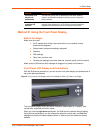
The status of the power outlets displays on the front panel LCD display as the
default display.
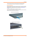
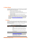
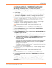
Connecting Devices to the 8-Port Ethernet Switch
To connect devices to the unmanaged Ethernet switch:
1. Use the included 1Ft Ethernet patch cable to connect Ethernet port 1 on the SLB
branch office manager to one of the switch ports.
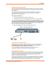
Figure 3-3. 8-Port Ethernet Switch
Note: The eight unmanaged Ethernet ports are not internally connected
to the other two Ethernet ports.
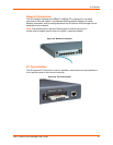
2. Use a standard Ethernet patch cable to connect another switch port to your
network.
3. Up to 6 more Ethernet devices may be connected to your network. Use standard
Ethernet patch cables from the Ethernet devices to the SLB device's switch ports.
An example of a standard Ethernet patch cable is the Lantronix 200.0062 RJ45 TO
RJ45 CAT5 CABLE (LAN PINNING) 6.6 Ft.
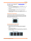
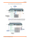
Typical Installations
Following are illustrations showing some typical ways to install the SLB branch office
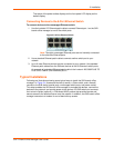
manager. In Figure 3-4, three serial devices (a server, a Cisco switch, and a firewall)
connect to the SLB device's serial ports, unmanaged switch ports, and power outlets.
This setup enables the SLB branch office manager to manage the devices, connect the
devices to the network, and provide power to the devices. An SLB switch port connects
the Lantronix Spider (optional), a “Distributed KVM” product that provides remote and
secure access to the attached server over the network. In addition, the SLB branch office
manager connects to a modem for out-of-band dial-up access.