


SLB™ Branch Office Manager User Guide 9
Accessing the Bootloader _______________________________________________ 264
Bootload Commands___________________________________________________ 264
User Commands __________________________________________________________ 264
Administrator Commands ___________________________________________________ 265
B: Security Considerations 266
Security Practice ______________________________________________________ 266
Factors Affecting Security _______________________________________________ 266
C: Safety Information 267
Safety Precautions ________________________________________________________ 267
D: Adapters and Pinouts 269
E: Protocol Glossary 275
F: Compliance Information 278
List of Figures
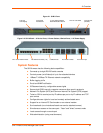
Figure 2-1. SLB 8 Front ........................................................................................................... 16
Figure 2-2. SLB 8 Back — 8 Device Ports, 4 Power Outlets, 8 Switch Ports;
1 AC Power Supply ......................................................................................................... 16
Figure 2-3. Device Port Connections ...................................................................................... 20
Figure 2-4. Console Port Connection ...................................................................................... 20
Figure 2-5. Network Connection .............................................................................................. 21
Figure 2-6. PC Card Interface ................................................................................................. 21
Figure 3-1. CAT 5 Cable Connection ...................................................................................... 25
Figure 3-2. Power Outlets ........................................................................................................ 26
Figure 3-3. 8-Port Ethernet Switch .......................................................................................... 27
Figure 3-4. SLB Installation Using the Integrated Ethernet Switch ......................................... 28
Figure 3-5. SLB Installation Using a Managed Switch ............................................................ 28
Figure 4-1. Front Panel LCD Display and Five Pushbuttons (Enter, Up, Down, Left, Right) .. 30
Figure 4-2. Beginning of Quick Setup Script ........................................................................... 37
Figure 4-3. Completed Quick Setup ........................................................................................ 39
Figure 5-1. Web Page Layout.................................................................................................. 41
Figure 13-1. SLB Branch Office Manager Configuration ....................................................... 206
Figure 13-2. Remote User Connected to a SUN Server via the SLB Device ....................... 207
List of Tables
Table 2-1. SLB Models ............................................................................................................ 15
Table 3-1. SLB Technical Specifications ................................................................................. 23
Table 4-1. Methods of Assigning an IP Address ..................................................................... 29
Table 4-2. Front Panel Setup Options with Associated Parameters ....................................... 31
Table 5-1. Actions and Category Options ............................................................................... 44
Table 14-1. Actions and Category Options ........................................................................... 213