


Chapter 13 xDSL Port Setup
IES-612-51A User’s Guide
113
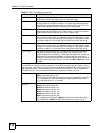
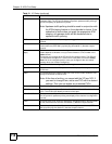
Alarm Profile Select the port’s alarm profile. The alarm profile defines alarm thresholds for the
ADSL port. The IES-612-51A sends an alarm trap and generates a syslog entry
when the thresholds of the alarm profile are exceeded (see Section 14.6 on
page 133).
IGMP Filter Profile The IGMP filter profile defines which multicast groups a port can join. Select a
profile of IGMP filter settings to assign to this port. Use the IGMP Filter Profile
screen to configure IGMP filter profiles (see Section 14.8 on page 135).
ADSL2/2+ feature These are features available with ADSL2/2+. The subscriber’s ADSL device
must also support the individual features in order to use them. At the time of
writing these features have not been fully tested and their performance and
interoperability cannot be guaranteed.
Annex L Enable Annex L to use reach extended ADSL2. This allows increased
connection distances.
Annex M Enable Annex M to use double upstream mode. This has the upstream
connection use tones 6 to 63.
Annex I Enable Annex I to use all digital mode. With Annex I, the ADSL connection uses
the full spectrum of the physical line and the user can not use POTS or ISDN
service. This increases the upstream data rate.
Note: The subscriber cannot use POTS or ISDN services when
you enable Annex I.
PMM Enable the Power ManageMent (PMM) feature to reduce the amount of power
used overall and reduce the instances of the connection going down. PMM
increases or decreases the transmission power based on line conditions. PMM
also decreases the number of service interruptions.
Select L2 to have the ADSL connection use power saving mode and reduce the
rate when there is no traffic. The rate comes back up when there is traffic.
Select L3 to use both power management modes L2 and L3. L3 puts the ADSL
connection to sleep mode.
L0 power mode uses no power reduction. See the ITU-T G.992.3 standard for
more on PMM and the power modes (states).
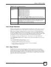
SRA Enable Seamless Rate Adaptation (SRA) to have the IES-612-51A
automatically adjust the connection’s data rate according to line conditions
without interrupting service.
Sudden spikes in the line’s noise level (impulse noise) can cause errors and
result in lost packets. Set the impulse noise protection minimum to have a buffer
to protect the ADSL physical layer connection against impulse noise. This
buffering causes a delay that reduces transfer speeds. It is recommended that
you use a non-zero setting for real time traffic that has no error correction (like
videoconferencing).
US INP Set the minimum upstream (US) impulse noise protection setting.
DS INP Set the minimum downstream (DS) impulse noise protection setting.
Max US TX PSD Specify the maximum upstream transmit power. The unit of measure is 0.1 dBm/
Hz; for example, to set the maximum upstream transmit power to -10 dBm/Hz,
set this value to -100.
Max DS TX PSD Specify the maximum downstream transmit power. The unit of measure is 0.1
dBm/Hz; for example, to set the maximum downstream transmit power to -10
dBm/Hz, set this value to -100.
L0 Time Set the minimum time (in seconds) that the ADSL line must stay in L0 power
mode before changing to the L2 power mode.
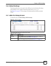
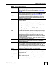
Table 20 xDSL Port Setting (continued)
LABEL DESCRIPTION