


IES-612-51A User’s Guide
195
CHAPTER 27
RFC 2684 Routed Mode
This chapter shows you how to set up 2684 routed mode service.
27.1 RFC 2684 Routed Mode
Use the RFC 2684 (formerly RFC 1483) routed mode to have the IES-612-51A add MAC
address headers to 2684 routed mode traffic from a PVC that connects to a subscriber device
that uses 2684 routed mode. You also specify the gateway to which the IES-612-51A sends the
traffic and the VLAN ID tag to add. See RFC-2684 for details on routed mode traffic carried
over AAL type 5 over ATM.
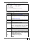
• Use the 2684 Routed PVC Screen to configure PVCs for 2684 routed mode traffic.
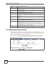
• Use the 2684 Routed Domain Screen to configure domains for 2684 routed mode traffic.
The domain is the range of IP addresses behind the subscriber’s device (the CPE or
Customer Premises Equipment). This includes the CPE device’s LAN IP addresses and
the IP addresses of the LAN computers.
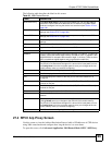
• Use the RPVC Arp Proxy Screen to view the Address Resolution Protocol table of IP
addresses of CPE devices using 2684 routed mode and configure how long the device is to
store them.
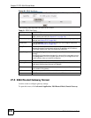
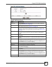
• Use the 2684 Routed Gateway Screen to configure gateway settings.
• For upstream traffic: Since the subscriber's device will not send out a MAC address, after
the IES-612-51A reassembles the Ethernet packets from the AAL5 ATM cells, the IES-
612-51A will append the routed mode gateway's MAC address and the IES-612-51A's
MAC address as the destination/source MAC address.
• For downstream traffic: When the IES-612-51A sees the destination IP address is
specified in the RPVC (or RPVC domain), the IES-612-51A will strip out the MAC
header and send them to the corresponding RPVC.
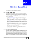
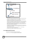
27.1.1 RFC 2684 Routed Mode Example
The following figure shows an example 2684 routed mode set up. The gateway server uses IP
address 192.168.10.102 and is in VLAN 1. The IES-612-51A uses IP address 192.168.20.101.
The subscriber’s device (the CPE) is connected to DSL port 1 on the IES-612-51A and the
2684 routed mode traffic is to use the PVC identified by VPI 8 and VCI 35. The CPE device’s
WAN IP address is 192.168.10.200. The routed domain is the LAN IP addresses behind the
CPE device. The CPE device’s LAN IP address is 10.10.10.10 and the LAN computer’s IP
address is 10.10.10.1. This includes the CPE device’s LAN IP addresses and the IP addresses
of the LAN computers.