


Chapter 13 xDSL Port Setup
IES-612-51A User’s Guide
114
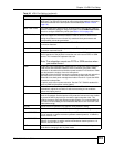
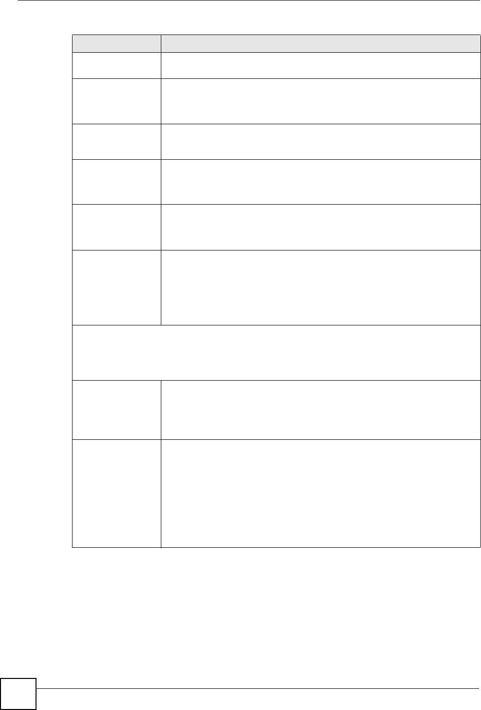
L2 Time Set minimum time (in seconds) that the ADSL line must stay in the L2 power
mode before reducing the power again in the L2 power mode.
L2 ATPR Set the maximum Aggregate Transmit Power Reduction (ATPR) in decibels (dB)
that is permitted in a L2 power reduction. The system can gradually decrease
the ADSL line transmission power while it is in the L2 power mode. This is the
largest individual power reduction allowed in the L2 power mode.
L2 ATPRT Set the maximum Aggregate Transmit Power Reduction Total (ATPRT) in
decibels (dB) that is permitted in the L2 power mode. This is the total transmit
power decrease that is allowed to occur in the L2 power mode.
Max L2 Rate Set the maximum transfer rate (in Kilobits per second) that is permitted while the
port is in the L2 power mode. The supported range is 32~4096 Kbps in 4 Kbps
increments. If you enter a number that is not a multiple of 4, the system uses the
next lower multiple of 4. If you enter 39, for example, the system will use 36.
Min L2 Rate Set the minimum transfer rate (in Kilobits per second) that is permitted while the
port is in the L2 power mode. The supported range is 32~4096 Kbps in 4 Kbps
increments. If you enter a number that is not a multiple of 4, the system uses the
next lower multiple of 4. If you enter 39, for example, the system will use 36.
L0 to L2 Rate Set the down stream transfer rate (in Kilobits per second) that serves as the
threshold for whether the port is to use the L0 or the L2 power mode. The
system changes from L0 mode to L2 mode when the downstream transfer rate
stays below this threshold for L0 Time. The system changes back from L2
mode to L0 mode when the downstream transfer rate goes above this threshold.
This rate must be less than or equal to one half of the Min L2 Rate and at least
16 Kbps.
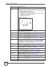
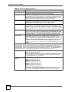
Use this part of the screen to mask carrier tones. Masking a carrier tone disables the use of that tone
on the ADSL port. Do this to have the system not use an ADSL line’s tones that are known to have a
high noise level. Each mask can use up to 8 hexadecimal digits (00000000~ffffffff). Each hexadecimal
digit represents 4 tones. The hexadecimal digit is converted to binary and a '1' masks (disables) the
corresponding tone. The most significant bit defines the lowest tone number in a mask.
US Carrier Mask0 represents tones 0~31.
Mask1 represents tones 32~63.
The most significant bit defines Tone 0. In other words, 0x00000001 means tone
31. For example, you could use 0xfffff000 to disable upstream carrier tones
0~19 and leave tones 20 ~ 31 enabled.
DS Carrier0
(32~255)
Mask1 represents tones 32~63
Mask2 represents tones 64~95
Mask3 represents tones 96~127
Mask4 represents tones 128~159
Mask5 represents tones 160~191
Mask6 represents tones 192~223
Mask7 represents tones 224~255
For example, use 0x01000000 in Mask2 to disable downstream carrier tone 71.
Use 0x03000000 in Mask2 to disable downstream carrier tones 70 and 71.
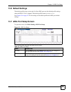
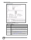
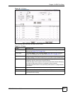
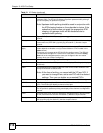
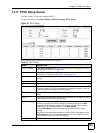
Table 20 xDSL Port Setting (continued)
LABEL DESCRIPTION