Chapter 3 Front Panel
IES-612-51A User’s Guide
52
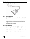
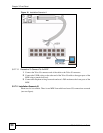
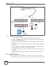
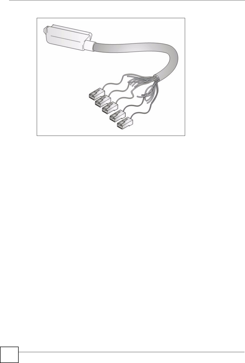
Figure 8 Telco-50 Cable with RJ-11 Connectors
3.2.5 Telco-50 Connections
The internal DSL splitters separate the voice signals from the DSL signals. They feed the DSL
signals to the IES-612-51A and divert the voice signals to the CO lines of the Telco-50
connector.
Connect the CO lines of the Telco-50 connector to the PBX or PSTN/ISDN switch.
Connect the USER lines of the Telco-50 connector to the subscribers' telephone wiring. In
most multi-tenant unit applications, the USER pins connect to the subscribers' telephone
wiring via Main Distribution Frame (MDF).
See the section on MDF scenarios and the pin assignments in the hardware specifications
appendix for details on Telco-50 connections.
3.2.6 ADSL Connections
Connect the lines from the user equipment (ADSL modems) to the Telco-50 connector USER
pins and the lines from the central office switch or PBX (Private Branch Exchange) to the
Telco-50 connector CO pins. Make sure that the USER line and the CO lines are not shorted
on the MDF (Main Distribution Frame).
The line from the user carries both the ADSL and the voice signals. For each line, the IES-
612-51A has a built-in splitter that separates the high frequency ADSL signal from the voice
band signal and feeds the voice band signal to the CO port.
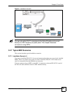
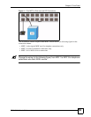
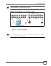
The following figure gives an overview on a possible installation scenario for the IES-612-
51A. Data and voice signals can coexist on the same telephone wiring.


