Installation
34 Avaya CMS Sun Ultra 5 Computer Hardware Installation, Maintenance, and Troubleshooting
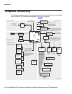
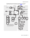
Peripheral connectivity
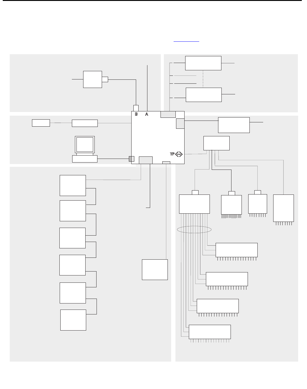
The following diagram shows how equipment is connected to the Ultra 5 when a SunSwift
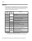
card is installed. The callouts are described in Parts list
on page 36.
Black Box
RS-449 - RS-232
interface converter
I
J
J
An HSI/P card is used
for up to four ACDs.
Asecond HSI/P card
is needed for eightACDs.
Black Box
RS-449 - RS-232
interface converter
System Console
Remote console
N
O
P
M
C
Monitor
AB
Keyboard
Mouse
Modem
Telephone line
to remote
maintenance center
8-port
NTS
8-port
NTS
no parallel
port
64-port
NTS
L
L
L
K
K
K
K
K
NTS patch panel
(16 RS-232 Ports)
NTS patch panel
(16 RS-232 Ports)
NTS patch panel
(16 RS-232 Ports)
NTS patch panel
(16 RS-232 Ports)
Network
hub
Serial port Ais
used for single ACD
SAI/P
expander box
(two maximum)
Sun
Ultra 5
Computer
SunSwift
HSI/P
SAI/P
Tape drive 1
(required)
Target 4
Tape drive 2
(optional)
Target 5
Ethernet port for switch
link, R7 and later
(supports up to eightACDs)
Disk drive 3
(optional)
Target 2
Disk drive 4
(optional)
Target 3
Disk drive 1
(optional)
Target 0
Disk drive 2
(optional)
Target 1
Parallel
printer
16-port
NTS
To terminals,
printers,
modems
To terminals,
printers,
modems
To terminals,
printers,
modems
To terminals,
printers,
modems
To terminals,
printers, or modems
H
S
T
Q
D
G
G
G
G
G
G
R
ultconp_sunswift.cdr
For detailed network hub and NTS
connectivity, see CMSTerminals,
Printers, and Modems, 585-215-874
For detailed switch link connectivity,see
CMS Switch Connections,Administration,
and Troubleshooting, 585-215-876
For detailed switch link
connectivity, see CMS Switch
Connections,Administration,
and Troubleshooting,
585-215-876
X.25 switch links
System console
External drives and
ethernet switch links


