


4-13
Cisco MGX 8220 Installation and Configuration
Release 5.0, Part Number 78-6430-03 Rev. D0, November 2003
Chapter
Frame Relay Service Modules (FRSMs)
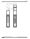
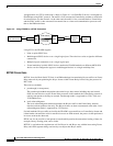
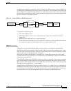
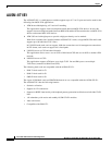
An application of a BSTUN connection is shown in Figure 4-6. A Bisync device, such as an IBM 3270,
is connected to a FRASM port using Bisync protocol. The traffic is first converted to Frame Relay and
then to ATM cells for transmission over the network. At the other end, the traffic is first converted back
to Frame Relay and the Bisync traffic is then extracted for transmission to a front end communication
processor and then to the IBM mainframe.
Figure 4-6 Using FRASM for a BSTUN Connection
Using BSTUN, FRASM supports
• Point-to-point Bisync lines.
• Multidropped Bisync devices over a single logical port. These can be assigned to different
connections.
• Multiple logical connections over a single logical port.
• Virtual multidrop in which Bisync devices attached to a FRAM on a different MGX 8220 shelf can
be configured to appear on multidropped devices on a single multidrop line.
FRAS Connections
FRAS BNN, short for Frame Relay Boundary Network Node, is a technique for encapsulating
SDLC/SNA traffic into Frame Relay frames (to RFC 1490) at one end of the connection only. At the
other end of the connection, the data is presented as Frame Relay. This is used for connecting an SDLC
device at one end to a Frame Relay device at the other.
SNA traffic received by the FRASM is converted first to a Frame Relay format and is then further
converted into cells for transmission over an ATM network, the ATM traffic is then converted back to
Frame Relay at the other end.
Using FRASM configured for FRAS BNN connections, many low speed SNA lines can be consolidated
into a smaller number of high-speed lines for fast transport through the network. In addition, FRAS
BNN can be used for high-speed links between IBM front end processors (FEPs). FEPs running under
Network Control Program (NCP) 7.1 support BNN.
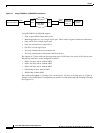
An application of a FRAS BNN connection is shown in Figure 4-7. An SDLC device is connected to an
FRASM port using SDLC protocol. The traffic is first converted to Frame Relay and then to ATM cells
for transmission over the network. At the other end, the traffic is first converted back to Frame Relay
for transmission to a front-end communication processor and then to the IBM mainframe.
Remote Bisynch
End User Device
Bisynch
FRASM
ATM network
Frame Relay
over ATM
MGX
8220
MGX
8220
FRASM
Bisynch
Front-end
Processor
NCP1
Mainframe
VTAM1
11761