


B-24
Cisco MGX 8220 Installation and Configuration
Release 5.0, Part Number 78-6430-03 Rev. D0, November 2003
Appendix B Specifications
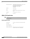
FRSM-HS2 Specification
FRSM-HS2 Specification
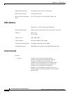
Errors and Alarm Handling
Line Alarms
• Control lead inactive
• Recovered clock does not match configured line rate
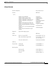
External Interface Specification
General
• Frame Relay Interface: Per ANSI T1.618, 2-octet header
• ATM layer: Per CCITT I.361 and ATM UNI v3.1
• AAL layer: AAL5 per Draft CCITT I.363.
• FR-cell interworking: Per Draft CCITT I.555 and I.36x.1, as summarized in ATM-to-Frame Relay
Interoperability Implementation Agreement v 1.0
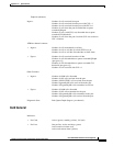
Physical Interface Specification
FRSM-VHS Front Card
• Card status indicator LEDs
–
Active (green)
–
Failed (red)
–
Standby (yellow)
• Line status indicator LEDs
–
Active and okay (green)
–
Active and local alarm (red)
–
Active and remote alarm (yellow)
• Reliability 85000 hours MTBF (target)
• Card size 7.25 in. x 16.5 in.
• Power 48V DC, 50W (estimate)
FRSM-HS2 Back Card
• Power: 5W @ 5V; 6W C @ -5V