


2-5
Cisco MGX 8220 Installation and Configuration
Release 5.0, Part Number 78-6430-03 Rev. D0, November 2003
Chapter
Power Entry Options
Each power entry module contains its own circuit breaker, which also acts as an ON/OFF switch. The
circuit breaker is closed by pressing in the large black button until it latches in the closed position. The
circuit breaker is opened by pressing the smaller red button. The DC PEM also includes a bracket that
is attached to the PEM to provide cable strain relief. See Chapter 7, “Installation and Start-Up” for
details.
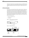
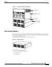
AC Powered Systems
In AC-powered systems, a separate AC power assembly is required. (See Figure 2-4 and Figure 2-5.)
This assembly is rack-mounted under the shelf cooling assembly in the rack and is available in both a
single and double AC source line version. The power assembly has a modular design and can be
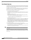
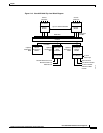
configured with up to six power supply modules, each module providing 875W of 48V DC power. The
power assembly can provide power for up to four Cisco MGX 8220 shelves, requiring three power
supply modules, or four for a (1 for N) redundant power supply configuration. The rear panel has four
connectors which supply 48V DC power to the shelves. The first three (1A, 2A, and 3A) connectors
also provide power monitoring information to the Cisco MGX 8220 shelf. Another three connectors
(1B, 2B, and 3B) on the rear panel provide monitoring information for the second half of the power
supply. Special cables are used from the rear of the power assembly to the rear of the shelves to feed
power and monitor data to the shelves.
The AC power assembly measures
• 5.25 inches (3 mounting units) high
• 17.45 inches wide
• 23 inches deep
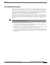
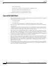
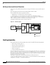
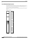
Figure 2-4 AC Power Assembly (front without grill)
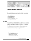
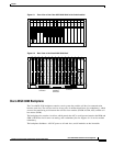
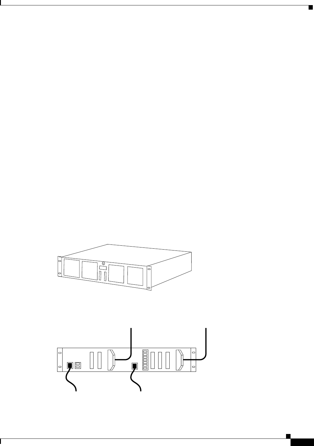
Figure 2-5 AC Power Assembly (rear)
H8246
Primary AC
source
Power and
monitor cables to
MGX 8220 shelf
Optional
secondary
AC source
Power connectors
& monitor
Monitor connectors
4A 3A 2A 1A3B 2B 1B
H8247