A-2
Cisco MGX 8220 Installation and Configuration
Release 5.0, Part Number 78-6430-03 Rev. D0, November 2003
Appendix A Cabling Summary
Frame Relay Cabling
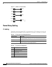
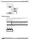
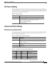
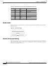
Figure A-1 IMATM T1/E1 Pigtail Cables
Frame Relay Cabling
T1 Cabling
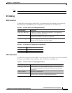
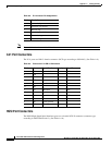
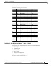
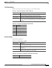
Trunk cables connect the customer DSX-1 crossconnect point or T1/E1 channel service unit to the
MGX 8220 node at the FRSM T1 back card (DB15-4T1). See Table A-3 and Table A-4 for details.
RJ-48
RJ-48
RJ-48
RJ-48
SMB
SMB
SMB
SMB
DB-15
BNC
S6188
Table A-3 T1 Trunk/Circuit Line Cabling Specification
Cable Parameter Description
Cable Type Western Electric 22 AWG, ABAM individually shielded twisted pair
(100-ohm balanced). Two pair per T1 line (one transmit and one receive).
Cable Connector Male DB-15 subminiature.
Max. Cable Length 533 ft (162 m) max. between the MGX 8220 shelf and the first repeater
or CSU. Selection of cable length equalizers.
Table A-4 T1 Connector Pin Assignments
Pin No. Description
1 Transmit, tip
2 Transmit, pair shield
3 Receive, tip
4 Receive, pair shield
9 Transmit, ring
11 Receive, ring


