


4-19
Cisco MGX 8220 Installation and Configuration
Release 5.0, Part Number 78-6430-03 Rev. D0, November 2003
Chapter
ATM UNI Service Module
AUSM LED Indicators
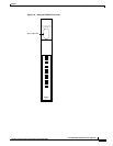
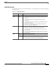
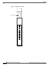
The AUSM LED indicators are described in Table 4-1. All LED indicators are located on the faceplate
of the front card.
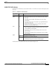
Table 4-1 AUSM LED Indicators
Type of LED Color Meaning
ACT Green On indicates the card set is in active mode.
STBY Yellow
• Slow blink without the Active LED indicates the card is in the
boot state.
• Fast blink with the Active LED indicates the card is being
downloaded.
• Fast blink indicates the service module is passing BRAM channel
information to the ASC.
• Steady yellow indicates the card is in Standby mode and the
firmware is executing ADMIN code.
FAIL Red
• Steady Red with Active and Standby LEDs off indicates either
the card is in the Reset condition or the card has failed.
• Steady Red with Active LED on indicates the card was active
prior to failing.
• Steady Red with Standby LED on indicates the card was standby
prior to failing.
PORT Green Green indicates the port is active.
Red Red indicates a local alarm on the port.
Yellow
• Yellow indicates a remote alarm on the port.
• Off indicates the port has not been activated (upped).