


A-1
Cisco MGX 8220 Installation and Configuration
Release 5.0, Part Number 78-6430-03 Rev. D0, November 2003
APPENDIX
A
Cabling Summary
Introduction
This appendix provides details on the cabling required to install the MGX 8220 shelf.
Note In all cable references, the transmit direction is from the MGX 8220 shelf, receive is to the
MGX 8220 shelf.
T3 Trunk Cabling
Trunk cables connect the T3 port on the BNM backcard to the BNI T3 port on the colocated BPX node.
See Table A-1 and Table A-2 for details.
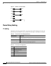
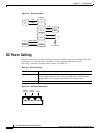
IMATM T1/E1 Connectors
The IMATM backcard can have eight RJ-48 connectors or eight SMB connectors. Connections are
made through short pigtail cables, two adapter cables, and two Y-cables for use with redundant IMATM
cards. (See Figure A-1.)
Table A-1 Trunk Cables
Cable Parameter Description
Type 75-ohm coax cable (RG-59 B/U for short runs, AT&T 734A for longer
runs). Two per T3 line (XMT and RCV).
Max. Length 450 feet max. between the BPX node and the MGX 8220 shelf.
Connector Terminated in male BNC; Rx is received from trunk, Tx is transmitted
to trunk.
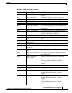
Table A-2 T3 Connector Pin Assignments
Connector Description
Rx BNC Receive T3 from trunk
Tx BNC Transmit T3 to trunk