


2-3
Cisco MGX 8220 Installation and Configuration
Release 5.0, Part Number 78-6430-03 Rev. D0, November 2003
Chapter
Cisco MGX 8220 Shelf
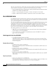
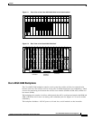
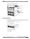
Figure 2-1 Front View of the Cisco MGX 8220 Shelf with Cards Installed
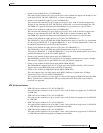
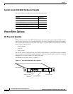
Figure 2-2 Rear View of the Cisco MGX 8220 Shelf
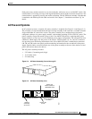
Cisco MGX 8220 Backplane
The Cisco MGX 8220 backplane contains a main system bus, and the cell bus for communication
between card slots. The cell bus consists of two pairs of unidirectional buses (for redundancy), which
are used for transferring cells between the cell bus slave modules (FRSM, AUSM, ASC) and the cell
bus master (BNM).
The backplane also contains a local bus, which permits the ASC to configure and monitor the BNM and
SRM, a BERT bus for bit error rate testing, and a redundancy bus for support of 1:N service module
redundancy.
The backplane distributes –48V DC power to all card slots, and all modules are hot insertable.
ACT
STBY
FAIL
LAN
ASC
• • • • •
• • • • •
ACT
STBY
FAIL
LAN
ASC
• • • • •
• • • • •
ACT
STBY
FAIL
PORT
BNM
ACO
HIST
T3
DC-A
DC-B
MIN
MAJ
ACO
HIST
• • • • •
• • • • •
ACT
STBY
FAIL
PORT
BNM
ACO
HIST
T3
DC-A
DC-B
MIN
MAJ
ACO
HIST
• • • • •
• • • • •
ACT
STBY
FAIL
PORT 1
PORT 2
PORT 3
PORT 4
4E1-C
FRSM
• • • • •
• • • • •
ACT
STBY
FAIL
PORT 1
PORT 2
PORT 3
PORT 4
4E1-C
FRSM
• • • • •
• • • • •
ACT
STBY
FAIL
PORT 1
PORT 2
PORT 3
PORT 4
4E1-C
FRSM
• • • • •
• • • • •
ACT
STBY
FAIL
PORT 1
PORT 2
PORT 3
PORT 4
4E1-C
FRSM
• • • • •
• • • • •
ACT
STBY
FAIL
PORT 1
PORT 2
PORT 3
PORT 4
4E1-C
FRSM
• • • • •
• • • • •
• • • • •
• • • • •
• • • • •
• • • • •
• • • • •
• • • • •
• • • • •
• • • • •
• • • • •
• • • • •
• • • • •
• • • • •
ACT
STBY
FAIL
PORT 1
PORT 2
PORT 3
PORT 4
4E1-C
FRSM
• • • • •
• • • • •
12345678910111213141516
H8243
T3E3-B T3E3-B
DB15-4T1 DB15-4T1 DB15-4T1 DB15-4T1 DB15-4T1 DB15-4T1 DB15-4T1 DB15-4T1 DB15-4T1 DB15-4T1
16151413121110987654321
ASCASC
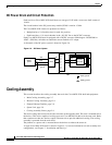
1B power
connector
1A power
connector
P1 cooling
assembly
connector
••
••
H8244