


A-8
Cisco MGX 8220 Installation and Configuration
Release 5.0, Part Number 78-6430-03 Rev. D0, November 2003
Appendix A Cabling Summary
Control and Clock Cabling
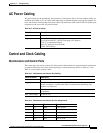
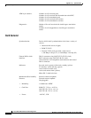
Modem Cable
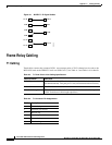
Figure A-4 shows a modem cable that is used for connecting modems to the MGX 8220 control and
maintenance ports.
Figure A-4 Null Modem Cable
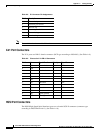
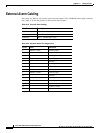
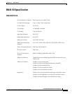
External Clock Input Cabling
The external clock input cable connects the external clock inputs through the T3/E3-D, T3/E3-B, and
SMF-155 EXT. TMG. connectors. The clock is 1.544 Mbps for T3/E3-D or 2.048 Mbps for T3/E3-D.
(See Table A-15 through Table A-18.)
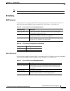
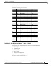
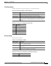
6 DSR DCE Data set ready
7 SG Both Signal ground
8 CD DCE Carrier detect
18
1
LL DTE Local loop
20 DTR DTE Data term ready
21
1
RL DTE Remote loop
22
1
RI DCE Ring indicator
1. Used on control port cable only.
Table A-14 Maintenance and Control Port Pin Assignments (continued)
Pin No. Name Source Description
1
7
2
3
6
20
1
7
2
3
6
20
S6189