


2-17
Cisco MGX 8220 Installation and Configuration
Release 5.0, Part Number 78-6430-03 Rev. D0, November 2003
Chapter
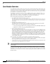
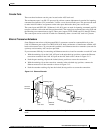
Core Module Overview
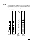
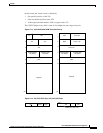
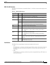
In this format, the virtual circuit is defined by
• Slot specific position of the VPI
• 4-bit slot number position of the VPI
• 10-bit logical channel number (LCN) assigned as the VCI
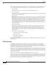
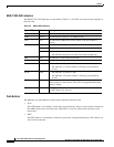
The CC/FFCI/Supervisory field is used for ForeSight bits and a Supervisory bit.
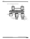
Figure 2-14 Cisco MGX 8220 ATM Trunk Cell Format
Figure 2-15 CC, FFCI, EFCI, Supv, PTI, and CLP Fields
1000
Slot#
LCN<7:0>
CC/FFCI/Supv
see below
PTI/EFCI/CLP
see below
HEC
Payload
53
6
5
4
3
2
1
Local VPI
10
VPI
VCI
HEC
53
6
5
4
3
2
1
VPI
Payload
LCN<11:8>
VCI
CC/FFCI/Supv
see below
PTI/EFCI/CLP
see below
H8254
FFCI Supv
msb
CLP
PTI
EFCI bit if msb is set
CC
H8255