


4-31
Cisco MGX 8220 Installation and Configuration
Release 5.0, Part Number 78-6430-03 Rev. D0, November 2003
Chapter
Circuit Emulation Service Modules
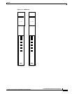
CESM 8-Port LED Indicators
The CESM 8-port LED indicators are described in Table 4-5. All LEDs are located on the faceplate of
the front card.
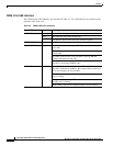
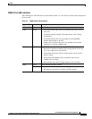
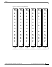
Table 4-5 CESM 8-Port LED Indicators
Type of LED Color Meaning
ACT Green On indicates the card set is in active mode.
STBY Yellow
• Slow blink without the Active LED indicates the card is in the
boot state.
• Fast blink with the Standby LED indicates the card is being
downloaded.
• Fast blink indicates the service module is passing BRAM
channel information to the ASC.
• Steady yellow indicates the card is in Standby mode and the
firmware is executing ADMIN code.
FAIL Red
• Steady Red with Active and Standby LEDs off indicates either
the card is in the Reset condition, the card has failed, or the card
set is not complete (no line module).
• Steady Red with Active LED on indicates the card was active
prior to failing
• Steady Red with Standby LED on indicates the card was
standby prior to failing.
• Both standby and red LED alight indicates self-test failure.
PORT Green Green indicates the port is active.
Red
• Red indicates there is local alarm on the port.
• Off indicates the port has not been activated (upped).