


5-18
Cisco MGX 8220 Installation and Configuration
Release 5.0, Part Number 78-6430-03 Rev. D0, November 2003
Chapter
Configuring the Clock Source
Configuring the Clock Source
IMATM has a T3/E3 interface and multiple T1/E1 interfaces. It is supposed to replace a physical long
distance T3/E3 ATM trunk by a group of long distance T1/E1 lines. Had there been a physical T3/E3
line, the clock sync info automatically reaches from one end to other along with T3/E3 data traffic.
Since we are breaking this continuation and replacing it with a group of T1/E1 lines, we need to have
some mechanism in IMATM to pass the clock across.
There are two commands in IMATM that can be used to change the clock configuration.
1. The cnfclksrc command lets you configure a primary clock source and a secondary clock source.
An on-board PLL generates a clock, phase locked to the primary clock source (If primary has gone
bad then phase is locked to the secondary. It switches back to primary when primary clock becomes
OK. Should both secondary and primary becomes unusable, PLL switches to backplane). This
phase-locked o/p then drives the entire card (for example, both T3 and N T1s on that card).
2. With the cnfln command you can configure the individual T1 lines as either Loop Clock or Local
Clock. When Local Clock is configured, it uses the clock selected using the cnfclksrc command,
whereas, Loop Clock is simply the clock recovered from T1/E1 receive. (Even when the T1/E1s
are configured in Loop Clock, the T3 transmit is still driven by the primary/secondary clock source
configured by cnfclksrc.)
3. The user needs to select which 10 sources should be used to drive all T1 and T3 lines on that card,
and then configure the clock source entering the cnfclksrc command.
Possible clock sources are 8-T1/E1 lines, T3/E3 line, or backplane 8 kKHz.
Note Primary from one of the DS1 lines and secondary from T3 does not make sense, since these two
mean different directions of passing clock sync.
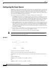
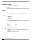
Example 1
---------------
---------------
T3 --- N* T1 --------------- N*T1 ---- T3
---------------
---------------
END A END B
In order to pass clock info from END A to END B:
END A T1 lines need to derive the clock derived from the END A T3.
END B derives clock from one of the incoming N T1s and drives the T3 transmit using this derived
clock.
Hence, we should have:
cnfclksrc -pri T3 -sec BP8K (or T3) -cur PRI ; at END A
and
cnfclksrc -pri DS1_1 -sec DS1_2 -cur PRI ; at END B