


A-7
Cisco MGX 8220 Installation and Configuration
Release 5.0, Part Number 78-6430-03 Rev. D0, November 2003
Appendix A Cabling Summary
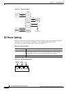
AC Power Cabling
AC Power Cabling
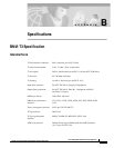
AC power cables can be provided by the customer or ordered from Cisco. Several standard cables are
available. (See Table A-12.) AC cables with other plugs or different lengths can be special ordered. For
users who wish to construct their own power cables, the cable must mate with an IEC320 16/20A male
receptacle on the rear of the AC power module.
Control and Clock Cabling
Maintenance and Control Ports
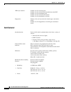
The control ports are used to connect one of the nodes in the network to a control terminal, workstation,
or modem connections for remote alarm reporting or system monitoring. Refer to Table A-13 and
Table A-14 for details on these cables.
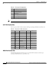
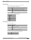
Table A-12 AC Power Cables
Cable Parameter Description
Cable Provided with 8 ft (2.3 m) of 3-conductor wire with plug.
Plug: customer end 20A NEMA L620, 3-prong plug (domestic)
13A 250 Vac BS1363, 3-prong fused plug (UK, Ireland)
CEE 7/7 (Continental Europe)
AS3112 (Australia, New Zealand)
CEI23-16/VII (Italy)
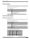
Table A-13 Maintenance and Control Port Cabling
Cable Parameter Description
Interface RS-232 DCE ports.
Suggested cable 24 AWG, 25-wire. A straight-through RS-232 cable is used for a terminal or
printer connection. A null modem cable is needed when interfacing with
modems on either port.
Cable connector DB-25, subminiature, male. Table A-14 contains a list of the port pin
assignments.
Max. cable length 50 feet (15 m)
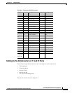
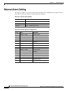
Table A-14 Maintenance and Control Port Pin Assignments
Pin No. Name Source Description
1 FG Both Frame ground
2 TxD DTE Transmit data
3 RxD DCE Receive data
4 RTS DTE Request to send
5 CTS DCE Clear to send