


7-14
Cisco MGX 8220 Installation and Configuration
Release 5.0, Part Number 78-6430-03 Rev. D0, November 2003
Chapter
Connecting Power for DC Systems
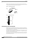
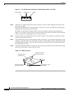
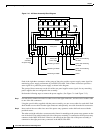
Figure 7-9 48V DC Male Power Receptacle Viewed Facing the Rear of the Shelf
Step 3
Attach the two supplied female Euro-block connectors to the two cables supplying DC power to the
power entry modules.
The cables should have three insulated number 12 AWG wires (solid or stranded) with the insulation
stripped back 0.25 inch (6 mm) on each wire.
Test which way the female connector attaches to the male connector using the pin assignments in
Figure 7-9 as a guide. For each cable, insert each of the wires into their correct holes in the connector
and secure each wire by tightening the screws in the connector.
Step 4 Connect a cable to each of the power entry module connectors. The connectors are polarized so they
cannot be inserted the wrong way.
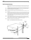
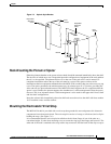
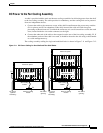
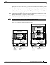
Step 5 Use the PEM cable clamp to secure the power cable. (See Figure 7-10.) Place the cable clamp over the
connector so that the small hole is positioned over the boss on the PEM. Secure by attaching the clamp
to the PEM with the captive screw. The cable clamp can be dressed to the left or right and secured to
the clamp using a tie wrap.
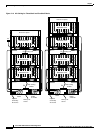
Step 6 If the redundant PEM module is not used, the cover power entry module must be installed in the empty
position to ensure proper cooling of the rear cards.
Figure 7-10 PEM Cable Clamp
Positive ground Safety ground
-48VDC
H8282
Position over boss on
power entry module
Use screw to attach to
power entry module
Use tie wrap to secure
power cable
Connector shows
through here
H8283