


A-6
Cisco MGX 8220 Installation and Configuration
Release 5.0, Part Number 78-6430-03 Rev. D0, November 2003
Appendix A Cabling Summary
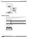
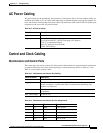
DC Power Cabling
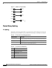
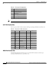
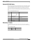
Figure A-2 RJ-48 Connectors
DC Power Cabling
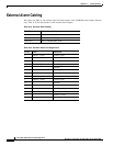
DC power connections are made to the DC power entry modules at the rear of the MGX 8220 shelf.
(See Figure A-3.) See Table A-11 and Table A-12 for acceptable cable and wire types.
DC wiring is generally provided by the customer. (See Table A-11.)
Figure A-3 DC Power Connections
TTIP
TRNG
RJ-48 Pins
RRNG
RTIP
ground/shield
2
1
5
4
3
6
7
8
IN
IN
TEST-RNGP
TEST-TIP
IN
IN
OUT
OUT
11763
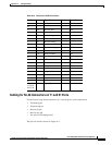
Table A-11 DC Power Wiring
Cable Parameter Description
Wiring Three conductor, 12 AWG recommended wire gauge, min. 60°C insulation
rating, copper conductors only. Solid or stranded wires. Wire insulation
stripped back 0.25 in. (6 mm) at the MGX 8220 connector end.
Connection Euro-block.
Positive
ground
Safety
ground
-48VDC
H10028