


6-4
Cisco MGX 8220 Installation and Configuration
Release 5.0, Part Number 78-6430-03 Rev. D0, November 2003
Chapter
VPI/VCI Mapping
VC Connections
For FRASM and AUSM VC connections, the user associates a logical channel number (LCN) with the
connection DLCI for a service module in a particular slot. The card’s slot number is used as the value
for the VPI and the LCN is used as the value for the VCI.
The VPI, therefore, is a number in the range of 5 to 14 (the range of permissible slots for service
modules in the MGX 8220).
The VCI range is determined by the service module type and is 16 to 271 for 4-port FRAM and AUSM
modules and 16 to 1015 for 8-port modules.
VP Connections
For AUSM VP connections, the situation is more complicated. The CPE port VPI value will most likely
be different from the network VPI. Depending upon the BNM interface format (UNI or NNI), the range
of VPI values is evenly divided among the 10 service module slots. During the process of adding a VP
connection, the user is asked to assign a VP ID where the VPID is an index corresponding to the VPI
within the assigned range.
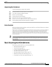
The ranges of VPID for the various service modules are shown in Table 6-1.
There are two methods that can be used to identify the network VPI associated with an AUSM VP
connection.
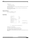
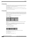
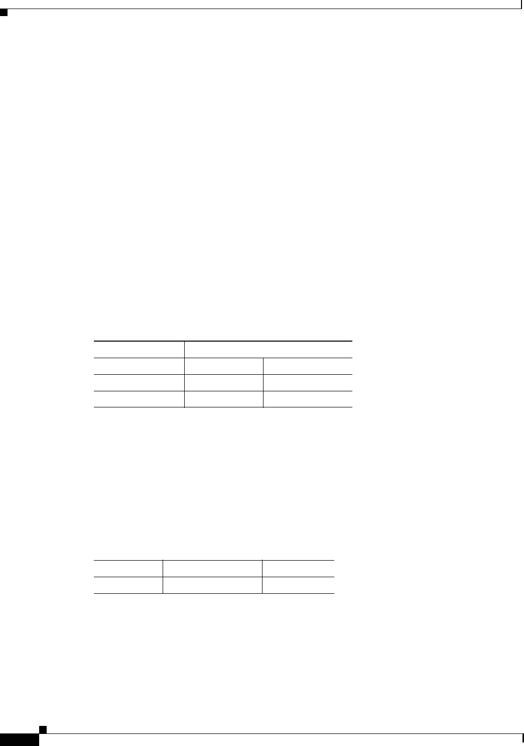
The first method is to enter the dspadrxlat command. This command lists all the VC and VP
connections currently existing on the shelf in slot number/channel number order showing the
connection type and the VPI value for each connection.
For example, the command
myshelf.1.4.ASC. a >
dspadrxlat
could result in the following response
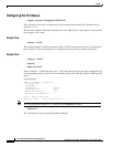
The second method is to calculate the VPI from the slot number and the VPID value.
For UNI interface format:
VPI = (slot number - 5) * 20 + (VPID - 1) + 16
For NNI interface format:
VPI = (slot number - 5) * 340 + (VPID - 1) + 16
Table 6-1 VPID Ranges
Interface Type VPID
AUSM-4T1E1 AUSM-8E1T1
UNI 1–20 1–20
NNI 1–255 1–340
Chan Connection Type VPI
1.8.16 vpConnection 76