


A-9
Cisco MGX 8220 Installation and Configuration
Release 5.0, Part Number 78-6430-03 Rev. D0, November 2003
Appendix A Cabling Summary
Control and Clock Cabling
T1/E1 Clock Cabling
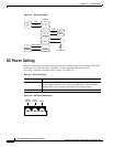
The DB-15 clock port can be used for accepting a T1 or E1 BITS clock input.
.
E1 Clock Cabling
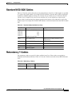
T3E-B, T3/E3-D, or SMF-155
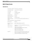
Table A-15 External Clock Cabling—T3/E3-D or SMF-155
Cable Parameter Description
Cable type Western Electric 22 AWG, ABAM individually shielded twisted pair
(100 ohm balanced). One pair per T1 line (one receive).
Cable connector Male DB-15 subminiature. Refer to Table A-16 for pinouts.
Max. cable length 533 ft (162 m) max. between the MGX 8220 shelf and the first repeater
or CSU. Selection of cable length equalizers is used. Wire buildout is
required.
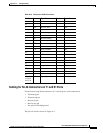
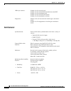
Table A-16 T1 Connector Pin Assignments for EXT. TMG
Pin No. Description
1
2 Transmit, pair shield
3 Receive, Tip
4 Receive, pair shield
9
11 Receive, Ring
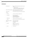
Table A-17 E1 Clock Cabling—T3/E3-B
Cable Parameter Description
Cable type 75-ohm coax cable for unbalanced connection. One cable pair
(1 receive) per E1 clock input.
Cable connector One female BNC for unbalanced connection; male DB-15 for balanced
connection.
Max. cable length Approx. 100 meters max. between the MGX 8220 shelf and the first
repeater or CSU. Equalizer for cable length.
Table A-18 E1 Connector Pin Assignments for EXT.TMG (unbalanced)
Connector Description
Rx BNC Receive E1 from trunk