


A-10
Cisco MGX 8220 Installation and Configuration
Release 5.0, Part Number 78-6430-03 Rev. D0, November 2003
Appendix A Cabling Summary
External Alarm Cabling
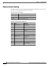
External Alarm Cabling
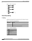
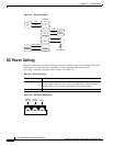
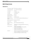
This cable (see Table A-19) connects network alarm outputs to the LM-BNM alarm output connector
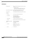
only. Table A-20 lists the pinouts for the network alarm outputs.
Table A-19 External Alarm Cabling
Cable Parameter Description
Interface Dry-contact relay closure
Wire 24 AWG, shielded, 6-pair
Connector DB-15, subminiature, male
Table A-20 Network Alarm Pin Assignments
Pin No. Alarm Description
1 Audible—major Normally open
2Common
9 Normally closed
4Visual—major Normally open
5Common
12 Normally closed
7unused n.c.
8unused n.c.
3 Audible—minor Normally open
11 Common
10 Normally closed
6Visual—minor Normally open
14 Common
13 Normally closed
15 unused n.c.