


7-23
Cisco MGX 8220 Installation and Configuration
Release 5.0, Part Number 78-6430-03 Rev. D0, November 2003
Chapter
Cable Management
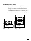
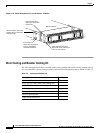
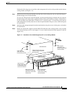
Perform the following steps to install the cable management kit on the cooling module and the booster
cooling module (see Figure 7-17).
Step 1 Install the two short fan panel brackets onto the sides of the cooling unit, one on each side using two
thread forming screws for each bracket.
If a rear rail is being used to mount the plenum, use the protruding flange to attach to the rail using two
thread forming screws and washers (supplied with the cooling unit install kit). If there is limited access,
use the procedures described under “Limited Access” section on page 7-10. Install the power and fan
cable management assembly onto the two short fan panel brackets using two screws with locking nuts
for each bracket.
Step 2 Install the cable management panel onto the outer brackets using four screws, locking nuts, and washers
for each bracket.
Step 3 Install one or both cable supports onto the MGX 8220 shelf above the cooling module, using a number
10-32 thread forming screw for each support. Use two washers between the cable supports on the left
support only.
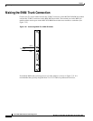
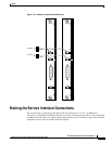
Figure 7-17 Installation of the Cable Management Kit on the Cooling Module
Cable management
panel, attach with
10-32 screws, locking
nuts and washers
Cooling assembly or
booster assembly
Short fan panel
bracket, attach with
10-32 thread forming
screws and washers
AXIS shelf
Attach bracket to rear rail (if
present) using 10-32 thread
forming screws
Power & fan cable
management assembly,
attach with 10-32 screws
and lock nuts
Cable support,
attach with 10-32
thread forming screws
Cable support,
attach with 10-32
thread forming screws
and two washers
LH
RH
H8289
MGX 8220 shelf