


7-15
Cisco MGX 8220 Installation and Configuration
Release 5.0, Part Number 78-6430-03 Rev. D0, November 2003
Chapter
Connecting Power for DC Systems
DC Power to the Fan Cooling Assembly
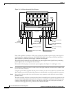
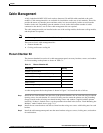
A cable is provided with the main and booster cooling assemblies for delivering power from the shelf
to the fan cooling assembly. The cable provides for redundancy, and the cooling unit can be powered
from two independent shelves.
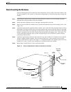
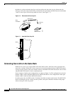
1. Connect the cable to the connector on rear of the shelf located between the power entry modules
(P1 for primary and P3 for redundant). When fully inserted, the cable will latch into place
preventing accidental removal. To unlatch the connector, use a small screwdriver to slide the catch
lever (located inside the slot on the connector) to the right.
2. Connect the other end of the cable to the receptacle on the rear of the fan cooling assembly, P2. If
the redundant portion of the cable is not used, it should be dressed to the side using a cable bundle
or a cable management tray.
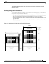
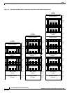
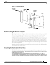
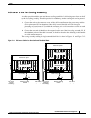
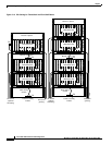
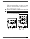
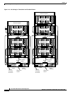
The cooling assembly cabling for single and multishelf racks is shown in Figure 7-11 and Figure 7-12.
Figure 7-11 DC Power Cabling for One-Shelf and Two-Shelf Racks
Main cooling
module
Plenum or spacer
AXIS shelf
DC source
(primary)
DC source
(optional
secondary)
Power to cooling
module
Main cooling
module
Plenum or spacer
AXIS shelf
AXIS shelf
DC source
(primary)
DC source
(optional
secondary)
Power to cooling
module
P2
P2
P3
P3
2B
2A
P1
1B
1A
P1
1B
1A
H8284
MGX 8220 shelf
MGX 8220 shelf
MGX 8220 shelf