


7-9
Cisco MGX 8220 Installation and Configuration
Release 5.0, Part Number 78-6430-03 Rev. D0, November 2003
Chapter
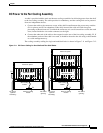
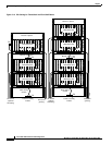
Rack-Mounting the MGX 8220 Units
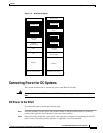
Rack-Mounting the Modules
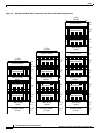
Start by mounting the lowest module first and work upwards. In AC systems, the lowest module is the
AC power module, in DC systems it is the main cooling module. Use the following steps to mount the
modules.
Step 1 Determine the vertical position in the rack where the shelf or shelves are to be installed. From this
determine the vertical position of the lowest module.
Step 2 Install disposable alignment screws in the upper mounting hole in the rack.
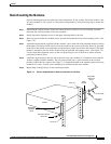
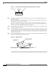
Step 3 Have one person lift the first module into its position and fasten the lower front mounting screws. (See
Figure 7-4.)
Step 4 Attach the angle brackets (supplied with the module), one on each side of the mounted module. Position
the brackets so that they can be used to secure the module to the rear rail of the rack. Holes are provided
in the side of the module to accommodate various distances of the rear rail from the front rail. The angle
bracket is attached to the side of the module using the provided self-tapping screws. (See Figure 7-4.)
Use the disposable alignment screws on the rear positioning as well as the front to ensure accurate
positioning of the first unit.
Step 5 Attach the angle bracket to the rear rail in the rack using four, number 10-32 machine screws and flat
washers (supplied with the module). The AC power module uses a special bracket at the rear that
provides a small shelf for support. (See Figure 7-4.) Attach the bracket to the mounting angle rack using
number10-32 screws. Screws are not mandatory to hold the bracket to the module.
Step 6 Repeat Step 2 through Step 5 for the remaining modules.
Figure 7-4 Use the Angle Bracket to Secure the Module to the Rack
Module
Front rail
Rear rail
Angle
bracket
Self-tapping
screws
10-32-screw
Disposable
alignment
screw
Disposable
alignment
screw
Decorative washer
and screw
H8277