


4-5
Cisco MGX 8220 Installation and Configuration
Release 5.0, Part Number 78-6430-03 Rev. D0, November 2003
Chapter
Frame Relay Service Modules (FRSMs)
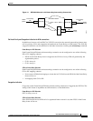
Frame Relay–to–ATM Direction
Each Frame Relay–to–ATM service interworking connection can be configured as one of the following
Discard Eligibility (DE) to cell loss priority (CLP) schemes:
• DE bit in the Frame Relay frame is mapped to the CLP bit of every ATM cell generated by the
segmentation process of the frame.
• CLP is always 0.
• CLP is always 1.
ATM–to–Frame Relay Direction
Each Frame Relay–to–ATM service interworking connection can be configured as one of the following
CLP to DE mapping schemes:
• If one or more ATM cells belonging to a frame has its CLP set, the DE field of the Frame Relay
frame will be set.
• DE is always 0.
• DE is always 1.
Setting up the cell loss priority option is accomplished through the MGX 8220 cnfchanmap (configure
channel map) command.
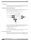
Congestion Indication
Frame Relay–to–ATM Direction
Each Frame Relay–to–ATM service interworking connection can be configured as one of the following
Forward Explicit Congestion Notification (FECN) to Explicit-Forward Congestion Indicator (EFCI)
schemes:
• FECN bit in the Frame Relay frame is mapped to the EFCI bit of every ATM cell generated by the
segmentation process of the frame.
• EFCI is always 0.
• EFCI is always 1.
ATM–to–Frame Relay Direction
Frame Relay–to–ATM service interworking connections use the following EFCI to FECN/BECN
mapping schemes:
• If the EFCI bit in the last ATM cell of a segmented frame received is set to 1, the FECN of the Frame
Relay frame will be set to 1.
• BECN is always set to 0.
Setting up the congestion indication option is accomplished through the cnfchanmap (configure
channel map) command.
Command/Response Mapping
Command/Response Mapping is provided in both directions.
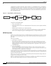
Frame Relay–to–ATM Direction
The FRSM maps the C/R bit of the received Frame Relay frame to the CPCS-UU least-significant bit
of the AAL5 CPCS PDU.