


CHAPTER
2-1
Cisco MGX 8220 Installation and Configuration
Release 5.0, Part Number 78-6430-03 Rev. D0, November 2003
2
Common Equipment Description
This chapter describes the required common equipment hardware that forms the core of the Cisco
MGX 8220 shelf. The optional service modules are described in Chapter 4, “MGX 8220 Service
Modules”. This chapter includes the following sections:
• Overview, page 2-1
• Cisco MGX 8220 Shelf, page 2-2
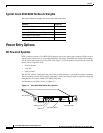
• Power Entry Options, page 2-4
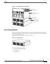
• Cooling Assembly, page 2-6
• Optional Cisco-Supplied Cabinet, page 2-9
• Core Module Overview, page 2-10
Overview
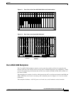
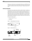
The Cisco MGX 8220 is a 19-inch rack-mountable shelf. This shelf provides 16 slots for holding the
modules (card sets) that provide the functionality. Each slot is designed to house two cards, a front card
and a back card. Cards are installed in a slot as a two card set. A backplane runs across all 16 slots to
provide signal connections between front and back cards, and between slots. The backplane also
provides power distribution to all slots from dual (redundant) power entry modules installed in the
bottom of the shelf.
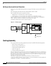
All external line connections are made on the back cards at the rear of the shelf. These include
Frame Relay lines, the ATM trunk line, and RS-232 lines for the control console.
The Cisco MGX 8220 includes the following common equipment:
• Cisco MGX 8220 shelf
–
Card cage
–
Backplane
–
Power entry module housing
• Core cards installed in the shelf
–
Cisco MGX 8220 shelf controller (ASC)
–
Broadband network module (BNM)
–
Optional service resource module (SRM)