


3-14
Cisco MGX 8220 Installation and Configuration
Release 5.0, Part Number 78-6430-03 Rev. D0, November 2003
Chapter
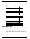
Structure of the MIBs
2. The cardInterface contains a list of physical interfaces and service types available on a card.
3. The cardSelftest contains a self-test enable/disable object, the interval between self-tests, and the
results of the last self-test.
4. The controlMsgCounter contains the current values of the control SAR counters (control frames
transmitted and received, control cells discarded, and so forth).
5. The sarChannelCounter contains the current values of the channel SAR counters. These counters
are for ATM cells and are maintained on a per VC basis.
cardSpecific
The cardSpecific section contains objects that are specific to a particular type of card. This section
contains seven subsections.
1. The bnmClockConfig contains the primary and secondary clock sources, the status and impedance
of the external T1/E1 clock input.
2. The bnmAddressTranslation contains shelf, slot, and channel mapping data.
3. The bnmATMCounters contain the ATM counters on the BNM card. These counters contain the
current values of ATM cells transmitted, ATM cells received, and so forth.
4. ASC LMI signaling information.
5. The fifth is currently unused.
6. Service module feature information.
7. Service module rate control configuration data.
axisLines
The axisLines section consists of four subsections.
1. The serialInterface contains information about the serial (maintenance and control ports) lines in
the shelf.
2. The ethernetInterface contains information about the Ethernet LAN port in the shelf.
3. The dsx1 contains information about configuration, alarm configuration, alarm status, and counters
for the DS1 lines.
4. The dsx3 contains information about configuration, alarm configuration, alarm status, and counters
for the DS3 lines.
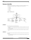
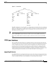
axisServices
The axisServices sections consists of the Cisco MGX 8220 service. This section contains information
about Frame Relay channel configurations, configurable parameters, and LMI signaling. This section
also contains similar MIB objects for ATM services.
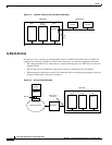
The services for Frame Relay are further organized as shown in Figure 3-7.