


2-8
Cisco MGX 8220 Installation and Configuration
Release 5.0, Part Number 78-6430-03 Rev. D0, November 2003
Chapter
Cooling Assembly
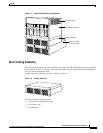
Booster Cooling Assembly
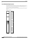
The booster cooling assembly is used in racks with more than two Cisco MGX 8220 shelves. It is
mounted above the shelves containing the main cooling assembly and below the shelves to which the
booster cooling is to be provided. The booster cooling assembly consists of fans that draw air from the
shelves below and exhaust air upward through the shelf or shelves above. Each booster supports an
additional two Cisco MGX 8220 shelves.
The booster cooling assembly measures
• 3.5 inches (2 mounting units) high
• 17.45 inches wide
• 22 inches deep
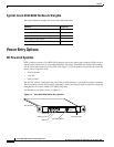
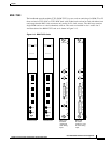
Plenum Exhaust Chamber
The plenum exhaust chamber is used in installations where the top of the unit must be enclosed. The
plenum chamber is mounted in the rack immediately above the shelf or shelves. The chamber exhausts
air from the shelf to the rear of the rack. The plenum chamber is the exhaust option recommended by
Cisco Systems.
The exhaust plenum chamber measures
• 3.5 inches (2 mounting units) high
• 17.45 inches wide
• 22 inches deep
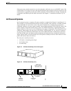
Spacer Unit
The spacer unit is an alternative method for exhausting air from the rack and can take the place of the
exhaust plenum. The spacer does not support the attachment of a cable management kit. If used, the
spacer unit is mounted in the rack immediately above the shelf or shelves.
The spacer unit measures
• 1.75 inches (1 mounting unit) high
• 17.45 inches wide
• 22 inches deep
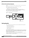
Cooling Assembly Power
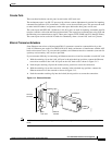
Power is supplied to a connector at the rear of the cooling assemblies by a cable running from the
bottom middle rear of the Cisco MGX 8220 shelf.
The assemblies provide output signals to the shelf. Using these signals, the cooling assembly
performance can be monitored by the BNM cards. The cable delivering DC power to the cooling
assembly from the Cisco MGX 8220 shelf also carries these signals to the BNM using the backplane.
The signals are such that the model of cooling assembly can be identified and the speed of each fan can
be monitored. Each fan generates a fixed number of square-wave pulses per revolution, allowing the
speed of the fan to be determined.