


1-5
Cisco MGX 8220 Installation and Configuration
Release 5.0, Part Number 78-6430-03 Rev. D0, November 2003
Chapter
Cisco MGX 8220 System Overview
Traffic Management
Traffic management is provided by the Cisco MGX 8220 Connection Congestion Management
(ACCM) feature. This feature is a virtual source/virtual destination rate-based closed loop feedback
scheme between nodes based on ForeSight and the ATM Forum Available Rate specification.
Periodically the round trip delay (RTD) of a cell to the far end and back is calculated for each actual
connection. The RTD is used to determine how frequently the ForeSight rate adjustment cells are sent
to the far end. Based on available bandwidth and current access rate, every few microseconds a
ForeSight cell is transmitted to the far end with any rate adjustments that are necessary to make better
use of the available bandwidth (rate is adjusted up, down, or fast down). The Cisco MGX 8220 MIB
includes rate (MIR, PIR, and QIR) and adjustment (up%, down%, and fast-down%) objects.
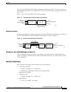
ATM Local Management Interface
ATM local management interface (ATM LMI) operates between the Cisco MGX 8220 shelf and the
Cisco BPX 8600 series. The ATM LMI is used to communicate change of status of semi-permanent
connections. The ATM LMI protocol conforms to the protocol specified in ITU-TS Recommendation
Q.2931, Sept. 1994. The ATM LMI also supports optional proprietary extensions to the ATM LMI for
the reporting of node information and BNI queue configurations.
The two end points of the ATM LMI signaling are an ATM LMI process in the BCC in the Cisco
BPX 8600 series and an ATM LMI process in the ASC in the Cisco MGX 8220 shelf. The ATM LMI
PDUs are transported over an AAL5 connection (VPI=3/VCI=31) between the BNI on the Cisco
BPX 8600 series side and the BNM on the Cisco MGX 8220 side. The ATM LMI process in the Cisco
BPX 8600 series can support ATM LMI connections for up to 16 Cisco MGX 8220 shelves.
The Cisco ATM LMI extension (which must be specifically enabled) uses a node update status message,
which is sent (Cisco BPX 8600 to Cisco MGX 8220 shelf or Cisco MGX 8220 shelf to Cisco BPX 8600)
whenever a change in node name, node IP address, major alarm status, or minor alarm status occurs.
The message can optionally contain Qbin status, thereby allowing Cisco MGX 8220 to configure the
BNI port egress queues.
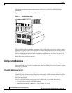
Cisco MGX 8220 Shelf
Physically, the Cisco MGX 8220 shelf consists of cards in a 19-inch rack-mounted shelf.
The shelf can be powered either from a -48V DC source or from a 220–240V AC source. The DC
version includes DC power entry modules that can be mounted in the shelf. The AC version requires an
external rack-mounted, AC power module. Both versions require a rack-mounted cooling assembly.
Multiple Cisco MGX 8220 shelves can be mounted in the same rack sharing power and cooling
assemblies. For more information on the shelf and power options, see Chapter 2, “Common Equipment
Description.”
The Cisco MGX 8220 shelf contains 16 slots. Each slot can accommodate a front card and a back card.
Six slots are reserved for common equipment modules. The common equipment modules are the core
modules required for the system to operate. Service modules (SMs) occupy the other 10 slots and
provide communication and transfer capability.
The front row of the shelf is used for function modules. These cards perform the more complex
functions within the unit (for example, Frame Relay to ATM conversion).
The back row is used for line modules. These cards provide interfaces to one or more transmission lines
connected to the Cisco MGX 8220 shelf (for example, the trunk line to the Cisco BPX switch or an
RS-232 line to a control terminal).