


5-3
Cisco MGX 8220 Installation and Configuration
Release 5.0, Part Number 78-6430-03 Rev. D0, November 2003
Chapter
Setting up a Frame Relay Connection
“B,” is attached to the other MGX 8220 shelf. This chapter describes how a Frame Relay connection
can be established to permit bidirectional communication between the Frame Relay equipment at “A”
and “B.”
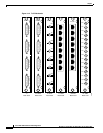
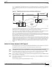
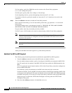
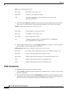
Figure 5-2 Frame Relay Connection through an MGX 8220 and BPX Network
To make the connection, the path from “A” to “B” is made up of three segments as shown in Figure 5.2.
When using the CLI, each segment must be established and configured separately.
Two segments span from the FRSM to the BNM on the MGX 8220 shelves. These segments are part
ATM and part Frame Relay with the conversion being made in the MGX 8220 shelves.
There is also an ATM trunk segment that spans the BPX backbone network from one of the BPX nodes
to the other BPX node, this segment terminates on a BNI feeder trunk in each node. This segment may
include intermediary BPX nodes (not shown in the diagram).
The links between the segments must be configured properly so that the three segments make up one
complete end-to-end connection from “A” to “B.” This process consists primarily of ensuring that the
VPI between the MGX 8220 shelf and its co-located BPX switch must contain the MGX 8220 slot
number of the FRSM and the VCI must contain the logical channel number assigned to the virtual
circuit.
Establish the Customer Equipment to BPX Segments
This procedure must be performed on the MGX 8220 at BOTH ends of the connection (“A” and “B”).
To establish an end-to-end Frame Relay connection, perform the following steps:
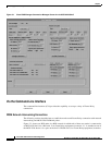
Step 1 On the MGX 8220 shelf, log in to the FRSM that is to be used for the Frame Relay connection.
Step 2 If not enabled, enable the T1 line to be used for the Frame Relay connection by entering the addln
command using the physical FRSM connector number (1 to 4) connected to the T1 line.
Step 3 If not configured, configure the T1 line to the Frame Relay equipment by entering the cnfln command.
Specify parameters as appropriate.
Step 4 If not enabled, enable the port to the Frame Relay equipment by entering the addport command using
the parameters as follows:
For port number, specify an unused port number (1 to 96).
BPX 8620
Backbone
Network
BPX
8620
F
R
S
M
Port
T1
Channel
A
A
BPX
8620
F
R
S
M
Port
T1
Channel
B
B
Customer Equipment
to BPX 8620
Customer Equipment
to BPX 8620
BPX 8620 to BPX 8620
BNI or
BXM-8-155
BNI or
BXM-8-155
S6187
MGX
8220
MGX
8220