


7-27
Cisco MGX 8220 Installation and Configuration
Release 5.0, Part Number 78-6430-03 Rev. D0, November 2003
Chapter
Readying the Cards
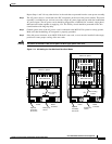
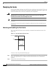
To install a front card, perform the following steps:
Step 1 Position the rear card guides over the appropriate slot at the top and bottom of the card cage.
Step 2 Gently slide the card all the way into the slot.
Step 3 Press the insertion/extractor lever until it snaps into the vertical position.
Note The card should slide in and out with only slight friction on the adjacent board’s EMI
gaskets. Do not use force. Investigate any binding.
Removing and Installing the Back Cards
Back cards are retained through two screws—one at the top of the faceplate and one at the bottom of
the faceplate.
To remove a back card, perform the following steps:
Step 1 Remove any cables connected to the back card.
Step 2 Use a flat screwdriver to unscrew the two retaining screws in the back card’s faceplate.
Step 3 Pull both of the two extractor levers out to the horizontal position; this will start the removal of the card.
Step 4 Gently pull the card out of the card cage.
.
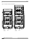
To install a back card, perform the following steps:
Step 1 Ensure the two extractor levers are in the “in” position. When the card is being inserted into the slot,
the levers should be vertical along the line of the back card.
Step 2 Position the rear card guides over the appropriate slot at the top and bottom of the card cage.
Step 3 Gently slide the card all the way into the slot.
Step 4 Tighten the two captive screws on the back card’s faceplate.
Tighten the upper and lower screws to prevent misalignment of the card. Do not overtighten the screws.
Tighten to secure the card.
Warning
Cards must be inserted in the correct slot positions. This is particularly true with back cards. If
service module back cards are inserted into slots intended only for ASC and/or BNM back cards
(slots 1, 2, 3, and 4), damage to the card and backplane can result.
If you accidentally attempt to insert a service module back card into slots 1, 2, 3, or 4 and have
difficulty in operating the shelf, examine the backplane pins and the backcard connector to see
if they have been bent or damaged.