


A-3
Cisco MGX 8220 Installation and Configuration
Release 5.0, Part Number 78-6430-03 Rev. D0, November 2003
Appendix A Cabling Summary
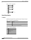
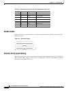
Frame Relay Cabling
Note Transmit direction is toward the T1 trunk.
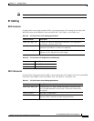
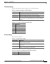
E1 Cabling
BNC Connector
E1 trunk cables connect the customer DSX-1 crossconnect point or E1 channel service unit to the
MGX 8220 node at the FRSM E1 back card (BNC-4E1). (See Table A-5 and Table A-6.)
DB-15 Connector
E1 trunk cables connect the customer DSX-1 crossconnect point or E1 channel service unit to the MGX
8220 node at the FRSM E1 back card (DB15-4E1). (See Table A-7 and Table A-8.)
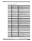
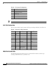
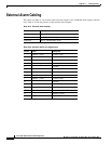
Table A-5 E1 Trunk/Circuit Line Cabling Specification
Cable Parameter Description
Cable Type: BNC-4E1 75-ohm coax cable for unbalanced connection. Two cables/pairs
(1 transmit, 1 receive) per E1 line.
Cable Connector Two female BNC for unbalanced connection; male DB15 for balanced
connection. See Tables A-2 and A-3 for pinouts.
Max. Cable Length Approx. 100 meters max. between the MGX 8220 shelf and the first
repeater or CSU. Equalizer for cable length.
Table A-6 E1 Connector Pin Assignments (unbalanced)
Connector Description
Rx BNC Receive E1 from trunk
Tx BNC Transmit E1 to trunk
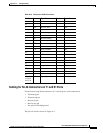
Table A-7 E1 Trunk/Circuit Line Cabling Specification
Cable Parameter Description
Cable Type: DB15-4E1 Western Electric 22 AWG, ABAM individually shielded twisted
pair (120-ohm balanced). Two pair per T1 line (one transmit and
one receive).
Cable Connector Male DB-15 subminiature.
Max. Cable Length 533 ft (162 m) max. between the MGX 8220 shelf and the first
repeater or CSU. Selection of cable length equalizers.