


2-21
Cisco MGX 8220 Installation and Configuration
Release 5.0, Part Number 78-6430-03 Rev. D0, November 2003
Chapter
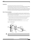
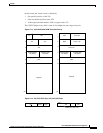
Core Module Overview
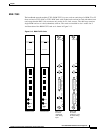
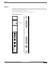
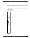
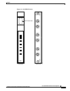
BNM-155 LED Indicators
The BNM-155 LED indicators are described in Table 2-3. All LEDs are located on the faceplate of the
front card.
Push Buttons
The BNM-155 has two push-buttons located on the faceplate of the front card.
• ACO
The ACO button is a momentary switch and is pressed during a major or minor alarm to deactivate
the audible alarm relays and to turn the ACO LED on. Any new alarm causes the relays to be
reactivated.
• HIST
The HIST button is a momentary switch and is pressed to extinguish the history LED if there is no
active alarm at the time.
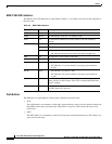
Table 2-3 BNM-155 LED Indicators
Type of LED Color Meaning
ACT Green On indicates the card set is in active mode.
STBY Yellow On indicates the card set is in standby mode.
FAIL Red On indicates the BNM-155 card set has failed or the line module is
missing.
PORT Green Green indicates the port is active.
Yellow Yellow indicates a remote alarm on the port.
Red
• Red indicates a local alarm on the port.
• Off indicates the port has not been activated (brought up).
MIN Red On indicates a minor alarm in the node.
MAJ Red On indicates a major alarm in the node.
DC-A Green
• On indicates “A” power is OK.
• Off indicates “A” power module is missing or present but at
0volts.
DC-B Green
• On indicates “B” power is OK.
• Off indicates “B” power module is missing or present but at
0volts.
ACO Yellow On indicates the ACO (audible cut-off) button has been pressed during
a major or minor alarm. This LED is extinguished when the alarm is
cleared.
HIST Green ON indicates a major or minor alarm has occurred since the last time
the HIST button was pressed.