


4-25
Cisco MGX 8220 Installation and Configuration
Release 5.0, Part Number 78-6430-03 Rev. D0, November 2003
Chapter
Inverse Multiplexer for ATM Trunk Module
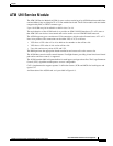
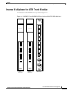
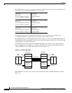
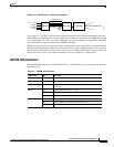
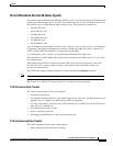
Figure 4-13 IMATM Used with Remote MGX 8220
Up to eight T1 or E1 links in the inverse multiplexed channel can be configured depending upon the
bandwidth desired. Bandwidth of T1 links range from 1.54 Mbps for one link to 12.35 Mbps for all eight
links. Bandwidth of E1 links range from 2 Mbps for one link to 16 Mbps for all eight links. The BNI
port bandwidth is configured to match the IMATM bandwidth.
Additional links can be provisioned to provide some protection against link failure. To achieve this, the
BNI trunk should be programmed to have a statistical reserve equal to the bandwidth of the extra links.
In the event of a link failure, a minor alarm occurs but no rerouting. Without this feature, a single link
failure will cause a major alarm and all connections will be rerouted over another trunk.
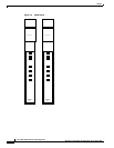
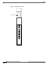
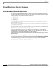
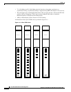
IMATM LED Indicators
The IMATM LED indicators are described in Table 4-3. All LED indicators are located on the faceplate
of the front card.
T1, E1 or T3
Service
Interface
Lines
Long Distance
IMA Trunk
BPX 8620
Broadband ATM Service
S6177
MGX 8220
MGX 8220
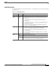
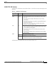
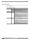
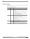
Tab le 4- 3 IM ATM LED Indic ato rs
Type of LED Color Meaning
ACT Green On indicates the card set is in active mode.
STBY Yellow On indicates the card set is in standby mode.
FAIL Red On indicates the IMATM card set has failed or the line module
is missing.
PORT Green Green indicates the line is active.
Yellow Yellow indicates a remote alarm on the line.
Red Red indicates a local alarm on the line.
HSPORT Green Green indicates the line is active.
Yellow Yellow indicates a remote alarm on the line.
Red Red indicates a local alarm on the line.