


7-12
Cisco MGX 8220 Installation and Configuration
Release 5.0, Part Number 78-6430-03 Rev. D0, November 2003
Chapter
Rack-Mounting the MGX 8220 Units
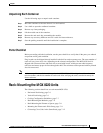
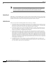
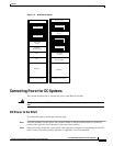
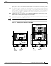
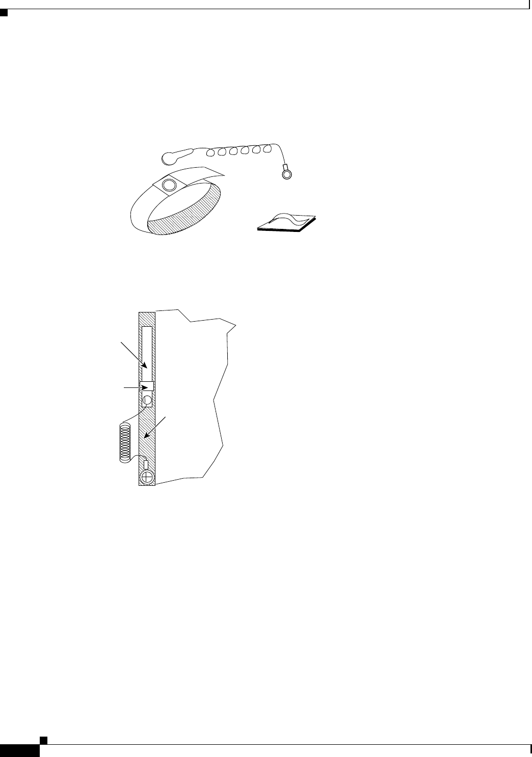
the adhesive surface and attach the clip to the front of the unit above the ring lug. Mount the clip
sideways to allow the strap to be held in a position that will not interfere with the removal of the number
1 card. Use the clip to store the strap when not in use. (See Figure 7-7.)
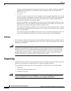
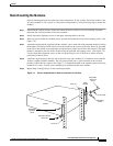
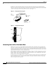
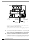
Figure 7-6 Electrostatic Wrist Strap Kit
Figure 7-7 Installed Wrist Strap Kit
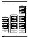
Colocating Cisco Units in the Same Rack
Different Cisco units, for example, MGX 8220 shelf, BPX switch, and ESP, can be colocated in the
same rack or cabinet. When this is done, however, the inclusion and positioning of MGX 8220 power,
cooling, booster, plenum, and spacer modules relative to the MGX 8220 shelf must be the same as those
when the MGX 8220 shelf is used in a dedicated rack.
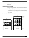
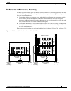
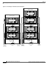
Some examples of multisystem configurations are shown in Figure 7-8. The configuration on the left
includes a BPX switch, redundant ESPs and two MGX 8220 shelves. The configuration on the right
includes a BPX switch and three MGX 8220 shelves.
In multisystem racks, the BPX switch, if included, should be mounted at the bottom. The MGX 8220
shelves including the power, cooling, booster, plenum, and spacer should be mounted in the proper
order at the top to allow for growth.
Strap
Clip with
adhesive back
Snap
connection
Coiled cord
Ring lug
#10
H8279
Strap
Clip
Cord
Lug
Left front
mounting
H8280