


2-24
Cisco MGX 8220 Installation and Configuration
Release 5.0, Part Number 78-6430-03 Rev. D0, November 2003
Chapter
Core Module Overview
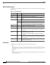
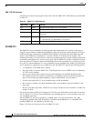
SRM-T1/E1 LED Indicators
All LEDs are located on the faceplate of the front card. The SRM-T1/E1 LED indicators are described
in Table 2-4.
AX-SRM-3T3
The SRM-3T3 service redundancy module provides bulk distribution of T1 circuits to the 4-port or
8-port T1 service modules. Rather than individually cable each of the 40 or 80 incoming T1/E1 lines to
an MGX 8220 edge concentrator, the MGX 8220 backplane is designed with a distribution bus that
allows an AX-SRM-3T3 to distribute T1s received “in bulk” to T1-based service modules. This
eliminates the need for T1 back cards for each service module and the associated cabling and potential
overloading of the digital cross-connect system port. The AX-SRM-3T3 provides a method to bring in
from one to three T3 interfaces that can be demultiplexed to their constituent T1s, providing up to 28,
56, or 80 T1s to be distributed to T1 service modules over the distribution bus. Both 4-port and 8-port
service modules are supported in any combination. The AX-SRM-3T3 supports the following features:
• 1:1 redundancy of the SRM with Y-cabling.
• The same features as the AX-SRM-T1E1, including bit rate error test (BERT) and 1:N redundancy
of T1/E1 service modules.
• Spare service module that can be used to provide redundancy for both bulk-distributed and
line-module-based service modules concurrently (a redundancy back card will be required for a
spare service module providing redundancy for line module-based service modules).
• No back card required for T1 service modules that use bulk distribution.
• Mix of service modules using bulk distribution with service modules using line modules in the
same shelf.
• Mix of 4-port and 8-port cards, with all 10 slots always available to service modules via either line
modules or bulk.
Out of the maximum possible 84 T1 channels (3 times 28), up to 80 channels can be active at any time.
Any T1 channel in a T3 line can be distributed to any four/eight port on a service module in any slots
5 to 14 without restriction.
The AX-SRM-3T3 can also be operated in “nonbulk mode” on a port-by-port basis. For a port
configured in nonbulk mode, bulk distribution is disabled and the SRM acts as a AX-SRM-T1/E1
providing BERT and 1:N redundancy functions only.
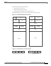
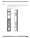
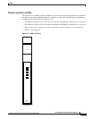
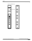
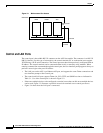
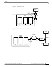
Figure 2-18 shows an illustration of the AX-SRM-3T3 cards.
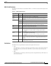
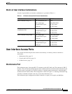
Table 2-4 SRM-T1/E1 LED Indicators
Type of LED Color Meaning
ACT Green On indicates the card set is in active mode.
STBY Yellow On indicates the card set is in standby mode.
FAIL Red On indicates the BNM-155 card set has failed or the line module
is missing.
1:N RED Green
• On indicates 1:N redundancy has been invoked.
• Off indicates 1:N redundancy is not active.
BERT Green On indicates the BERT function is active.