


1-16
Cisco VISM Installation and Configuration Guide
Release 3.0, Part Number OL-2521-01 Rev. D0, June 2004
Chapter 1 Overview of the VISM and VISM-PR Cards
Installing VISM Hardware and Software
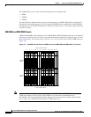
Installing a VISM Back Card
Complete the following instructions to install a VISM back card:
Step 1 Ensure that the two extractor levers are at the “in” position.
When you insert the card into the slot, the levers should be vertical or horizontal along the line of the
back card.
Step 2 Position the rear card guides over the appropriate slot in the chassis.
Step 3 Gently slide the card all the way into the slot.
Step 4 Tighten the two captive screws on the back card’s faceplate.
Step 5 Tighten the upper and lower screws to prevent misalignment of the card.
Note Do not overtighten the screws. Tighten them only enough to secure the card.
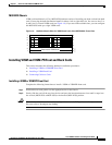
Connecting Cables to Cards
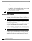
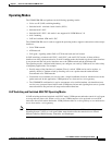
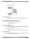
After you install the VISM front and back cards, connect the T1 or E1 cables to the RJ-48 or SMB
connectors on the back cards. The T1 and E1 cables connect the eight ports on the back cards to the voice
T1 or E1 lines. The T1 lines use RJ-48 connectors. The E1 lines use either RJ-48 or SMB connectors.
Note In all text references to cables, “transmit” refers to a cable used for data moving away from the VISM
card, and “receive” refers to a cable used for data moving toward the VISM card.
Cabling for RJ-48 Connectors on T1 and E1 Ports
For T1 and E1 ports that connect through an RJ-48 connector, each connector has:
• Transmit TIP (TTIP) pin
• Transmit RING (TRNG) pin
• Receive TIP (RTIP) pin
• Receive RING (RRNG) pin
• Two pins for shielded ground