


1-17
Cisco VISM Installation and Configuration Guide
Release 3.0, Part Number OL-2521-01 Rev. D0, June 2004
Chapter 1 Overview of the VISM and VISM-PR Cards
Installing VISM Hardware and Software
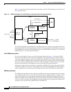
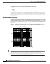
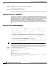
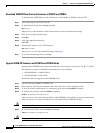
The connector wiring is shown in Figure 1-10.
Figure 1-10 RJ-48 PIN Connector
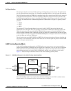
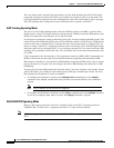
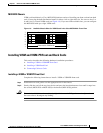
Cabling for SMB Connectors on E1 Ports
When you use the E1 VISM back card with SMB cables, the E1 trunk cables connect the customer
DSX-1 cross-connect point or E1 channel service unit (CSU) to the node using 75-ohm coaxial cable
fitted with SMB connectors.
Removing VISM and VISM-PR Front and Back Cards
This section describes the following hardware installation procedures:
• Removing a VISM or VISM-PR Front Card
• Removing a VISM Back Card
Removing a VISM or VISM-PR Front Card
Step 1 Insert a small, flat-blade screwdriver into the slot in the insertion/extractor lever and press until the latch
springs open, to approximately 10°.
Step 2 Continue to lift the insertion/extractor lever to disconnect the connector.
Step 3 Gently pull the card out of the chassis.
Removing a VISM Back Card
Step 1 Remove any cables connected to the back card.
Step 2 Use a small, flat-blade screwdriver to unscrew the two retaining screws in the back card’s faceplate.
TTIP
TRNG
RJ-48 Pins
RRNG
RTIP
ground/shie
ld
2
1
5
4
3
6
7
8
IN
IN
TEST-RNGP
TEST-TIP
IN
IN
OUT
OUT
11763