


CHAPTER
6-1
Cisco VISM Installation and Configuration Guide
Release 3.0, Part Number OL-2521-01 Rev. D0, June 2004
6
Troubleshooting Tips
Use the following troubleshooting tools and techniques to assist you in maintaining your VISM card:
• “VISM Card LEDs” section on page 6-1
• “VISM and PXM Display, Log, and Diagnostic Loopback Path CLI Commands” section on page 6-2
• “VISM Alarms” section on page 6-5
• “UNIX Snoop Trace Tool” section on page 6-5
• “Symptoms and Solutions” section on page 6-5
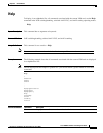
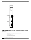
VISM Card LEDs
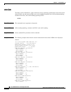
The VISM card uses the following three card status LEDs (see Figure 6-1) to indicate certain states:
• ACT—Green indicates the active state.
• STBY—Orange, or blinking orange, indicates one of the following:
–
VISM is in the standby state.
–
VISM is in the mismatch state.
–
VISM card DSPs are currently involved in the VISM card bootup.
• FAIL—Red indicates the failure state, or certain stages of the bootup process.
The VISM card uses eight line status LEDs (see Figure 6-1) to indicate the following states of the eight
T1 or E1 ports on the VISM back card:
• Green—A line has been added and there is no alarm on that line.
• Orange—A line has been added and there is a yellow alarm condition on the line.
• Red—A line has been added and there is one of the following conditions on the line:
–
Loss of signal (LOS) (red alarm condition)
–
Loss of frame (LOF)
–
Alarm indication signal (AIS)