


A-3
Cisco VISM Installation and Configuration Guide
Release 3.0, Part Number OL-2521-01 Rev. D0, June 2004
Appendix A VISM and VISM-PR Card Clocking Options
VISM Card as Primary Clocking Source
VISM Card as Primary Clocking Source
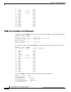
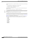
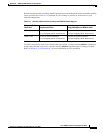
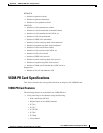
Figure A-2 shows the VISM card primary clocking source option in which the clock source originates
at the VISM side of the VISM/PXM interface.
Figure A-2 VISM Configured for Loop Clocking
The VISM card option originates clocking from one of the T1 or E1 lines on one of the VISM cards.
To configure the VISM card as the primary clocking source, complete the following steps:
Step 1 Use the cnfln command to configure line number 1—the line that is receiving the clocking source—for
loop clocking.
Step 2 Use the cnfln command to configure all remaining T1 or E1 lines on all VISM cards in the chassis for
local clocking.
Step 3 Use the cnfclksrc command to configure the PXM card as a service module clocking source and specify
VISM and its clocking line (line number 1) as the clocking source.
Note The VISM card allows you to configure the clock source on line 1 only. The VISM-PR card does not
have this requirement.
VISM-PR Card as Primary Clocking Source
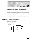
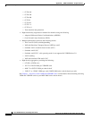
The VISM-PR card allows you to configure primary clocking from the following sources:
• Network clock—the local clock for the PXM1, PXM1E, or PXM45 module
• Any VISM-PR T1 or E1 line
• On-board oscillator
External BITS (T1/E1
)
Network (OC3)
Internal crystal
Clocking on T1/E1
line 1 to
PBX or CO
MGX 8850
VISM
V
ISM line #1 configured
f
or loop clocking, all other
V
ISM lines (including all
l
ines on other VISM cards)
c
onfigured for local clocking
MGX clock source configured for:
Service Module
Bus
51225