


6-5
Cisco VISM Installation and Configuration Guide
Release 3.0, Part Number OL-2521-01 Rev. D0, June 2004
Chapter 6 Troubleshooting Tips
VISM Alarms
VISM Alarms
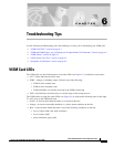
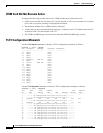
Table 6-1 describes VISM T1 and E1 card alarms.
Refer to T1.403 for DS1 and G.704 for E1 definitions of alarm states. Alarms are propagated to the
remote end over the ATM network in accordance with ATM specifications.
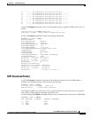
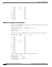
UNIX Snoop Trace Tool
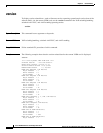
Use the UNIX snoop trace tool to assist in diagnosing a problem. The snoop command can determine if
there is any activity between the VISM and the call agent. The following example shows the command
and a typical resulting terminal display:
snoop -x 42 -ta <ip address of CA> port <udp port of CA>
E.g snoop -x 42 -ta vismvsc1 port 2427
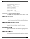
Symptoms and Solutions
This section includes possible solutions to the following possible symptoms:
• “VISM Card Did Not Become Active” section on page 6-6
• “T1/E1 Configuration Mismatch” section on page 6-6
• “DSP Download Failure” section on page 6-7
• “VISM Front Card/Back Card Mismatch” section on page 6-8
• “Cannot Use the cc Command to Access a VISM Card” section on page 6-9
• “VISM Card Resets Intermittently” section on page 6-9
• “VISM Card Does Not Accept a Firmware Download” section on page 6-9
• “Echo Is Heard on a Voice Call” section on page 6-9
• “VISM Card LEDs Are Not Lighted” section on page 6-9
Table 6-1 VISM T1 and E1 Card Alarms
Error Alarm Type
Down stream
(ATM side)
Up Stream
(TDM side) Comments
Link Failure—receive
LOS
1
LOS
1
1. LOS = Loss of service.
AIS
2
2. AIS = Alarm indication signal.
RAI
3
3. RAI = Remote alarm indicator.
RAI
3
returned on the transmit
line.
Receive RAI
3
Yellow RAI
3
None —
Receive LOF
4
4. LOF = Loss of frame.
—AIS
2
RAI
3
RAI
3
returned on the transmit
line.
Receive AIS
2
AIS
2
AIS
2
RAI
3
RAI
3
returned on the transmit
line.