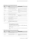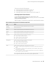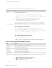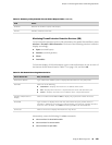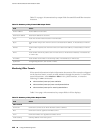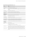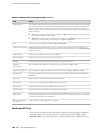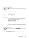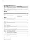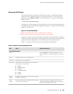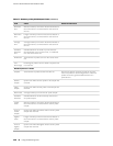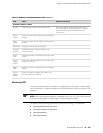
Table 74: Summary of Key IPSec Output Fields (continued)
ValuesField
Gateway address of the remote system.Remote Gateway
Direction of the IPSec tunnel: Inbound or Outbound.
Direction
Protocol supported: either Encapsulation Security Protocol (ESP) or Authentication Header and ESP
(AH+ESP).
Protocol
Numeric identifier of the IPSec tunnel.Tunnel Index
Prefix and port number of the local endpoint of the IPSec tunnel.Tunnel Local Identity
Prefix and port number of the remote endpoint of the IPSec tunnel.Tunnel Remote
Identity
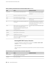
IPSec Statistics
Name of the service set for which the IPSec tunnel is defined.Service Set
Gateway address of the local system.Local Gateway
Gateway address of the remote system.Remote Gateway
Total number of bytes encrypted by the local system across the IPSec tunnel.ESP Encrypted Bytes
Total number of bytes decrypted by the local system across the IPSec tunnel.ESP Decrypted Bytes
Total number of bytes received by the local system across the IPSec tunnel.AH Input Bytes
Total number of bytes transmitted by the local system across the IPSec tunnel.AH Output Bytes
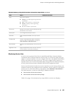
IKE Security
Responder's address.Remote Address
State of the IKE security association:
■
Matured—IKE security association is established.
■
Not matured—IKE security association is in the process of negotiation.
State
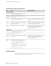
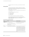
Random number sent to the remote node when the IKE negotiation is triggered. This number is
generated by means of an algorithm and information shared during the IKE negotiation. Cookies
provide a basic form of authenticity protection to help prevent denial-of-service (DoS) attacks.
Initiator Cookie
Random number generated by the remote node when it receives the initiator cookie. The remote
node sends the cookie back to the IKE initiator as verification that the negotiation packets were
received.
Responder Cookie
Using the Monitoring Tools ■ 141
Chapter 7: Monitoring the Router and Routing Operations


