SATO M-5900RV Operator and Technical Reference Manual Page 5-7
Section 5. Interface Specifications
PN 9001081
Rev. C
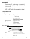
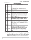
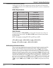
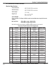
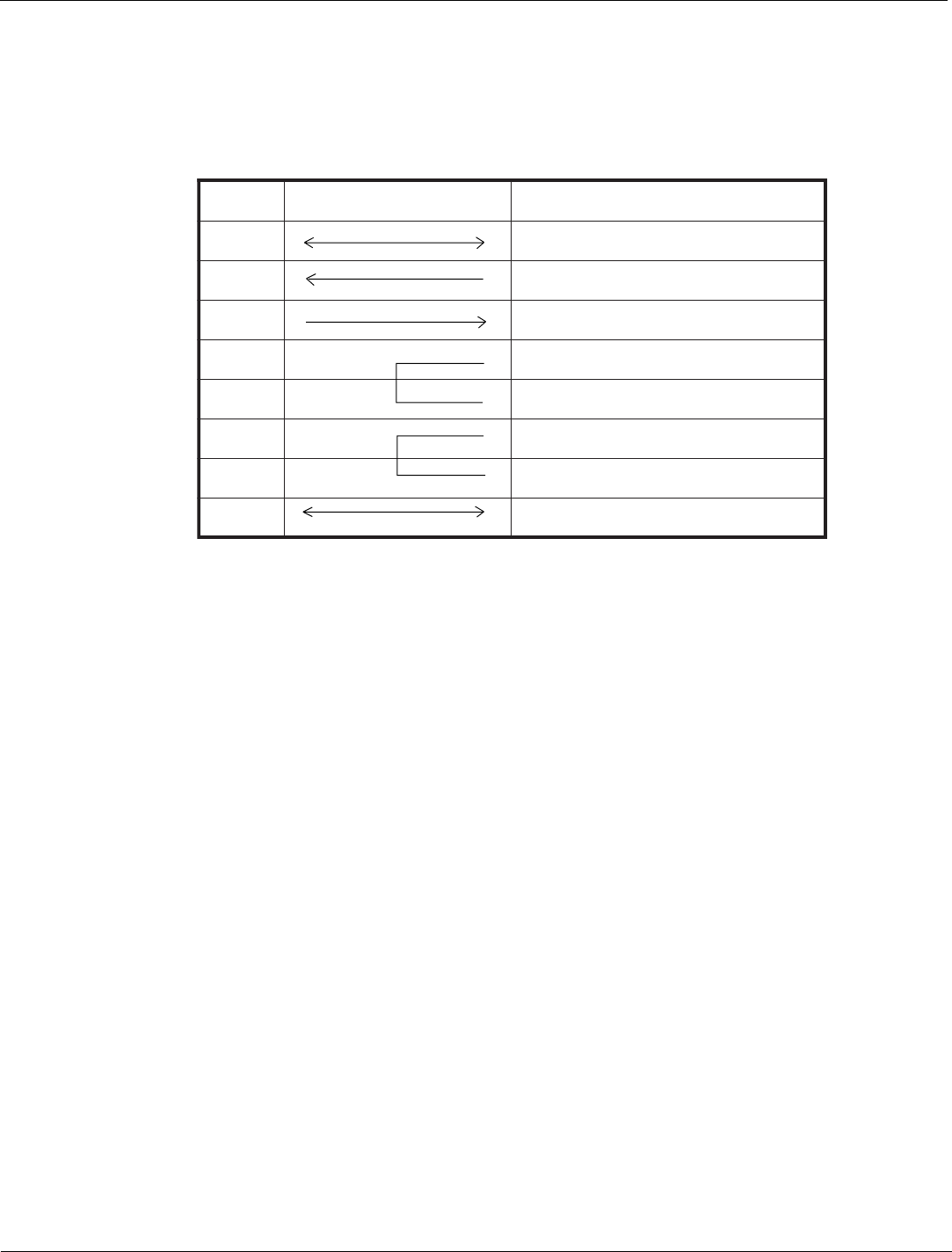
TSOHNOITCENNOCRETNIRETNIRP
GF)dnuorGemarF(GF1
DR)ataDtimsnarT(DT2
DT)ataDevieceR(DR3
)dneSottseuqeR(STR4
)dneSotraelC(STC5
)ydaeRteSataD(RSD6
)ydaeRlanimreTataD(RTD02
GS)dnuorGlangiS(GS7
Upon power up, if no error conditions are present, the printer will continually
send X-On characters at five millisecond intervals until it receives a transmission
from the host.
X-On/X-Off Flow Control (Cont.)
Cable Requirements
Data Streams
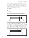
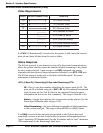
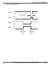
The data streams for X-On/X-Off are constructed in the same way as they are
for Ready/Busy flow control. The STX and ETX control characters must frame
the data stream.
NOTE: All characters, including STX, ESC, and ETX are in ASCII.
<STX><ESC>A..Job#1..<ESC>Z<ESC>A..Job#n..<ESC>Z<ETX>
Example: <STX><ESC>A..Job#1...<ESC>Z<ETX>XXXXX
Bi-Directional Communications
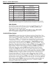
This is a two-way communications protocol between the host computer and the
printer, thus enabling the host to check printer status. When this protocol is
selected, there is no busy signal from the printer (pin 20, DTR is always high).
The host must request the complete status from the printer, including ready/busy.
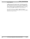
Whenever the host requests printer status it transmits an ENQ to the printer and
the printer will respond with its status within five milleseconds. If printing, it will
respond upon finishing the current label, then resume printing. In order for this
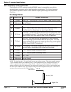
protocol to work properly, pin 6 (DTR) and pin 5 (CTS) must be held high by the
host. One way to ensure these pins are always in the correct state is to tie pin 20
(DTR) to pin 6 (DSR) and pin 4 (RTS ) to pin 5 (CTS) at the printer end of the
cable.


