


SATO M-5900RV Operator and Technical Reference Manual
Page 2-13
Section 2. Installation and Configuration
PN 9001081
Rev. C
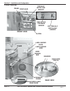
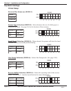
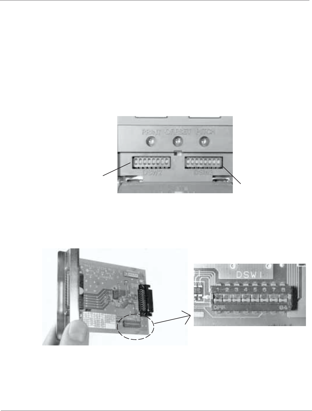
2.8 Dip Switch Settings
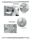
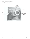
Two DIP switches (DSW2 & DSW3) are located underneath a flip-down cover on
the operation panel. These switches can be used to set:
Sensor Type
Head Check Mode
Hex Dump Mode
Receive Buffer Size
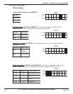
Protocol Code
Compatible Mode
Print Mode
Pitch Sensor
Backfeed
Print Start Signal
External Signal Type
Repeat Signal
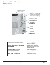
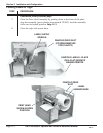
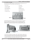
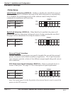
A third DIP Switch (DSW1) is located on a RS232 Serial Interface Card and is
used to set transmit/receive parameters. This card is installed by inserting it
through the slot in the back of the printer directly to the main PCB board. The
switches can be set by either removing the card or by opening the left side panel.
Each switch is an eight section "toggle" switch. The ON position is always to the
top. To set the switches, first power the unit Off, then position the DIP switches.
Finally after placing the switches in the desired positions, power the printer back
on. The switch settings are read by the printer electronics during the power-up
sequence. They will not become effect until the power is cycled
DSW2
DSW3
DSW1