SATO M-5900RV Operator and Technical Reference ManualPage 3-8
Section 3. Adjustments and Maintenance
PN 9001081
Rev. C
Replacing the Print Head
STEP PROCEDURE
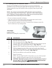
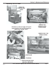
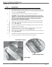
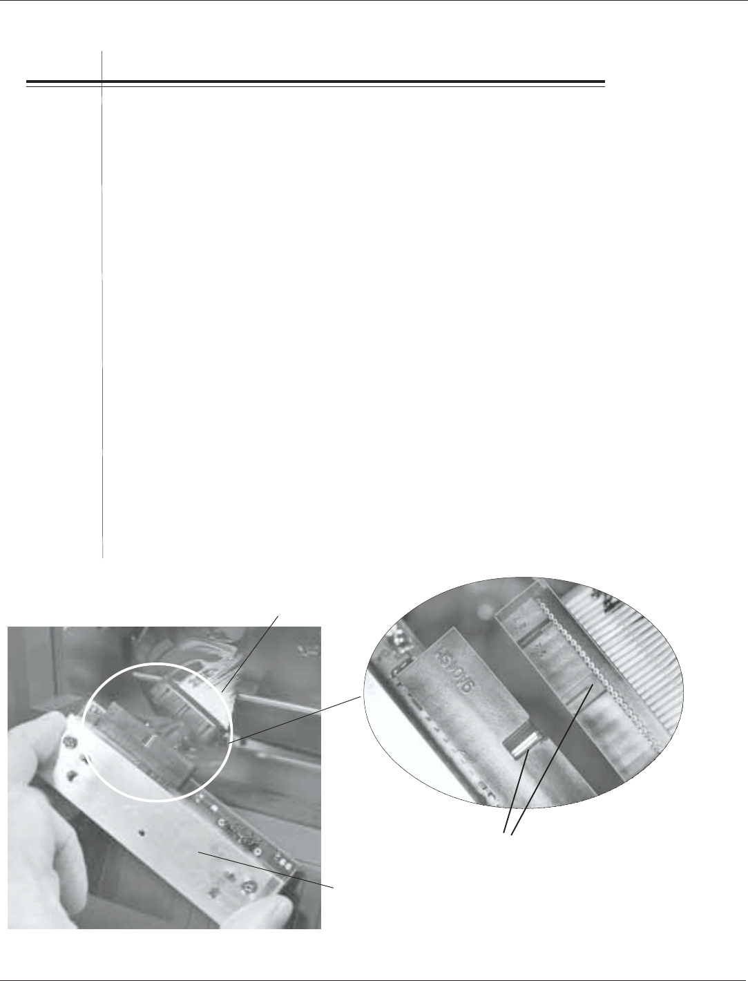
7. While holding the print head firmly from the sides, carefully disconnect
the cable at the back of the print head. Set the damaged print head and
tear bar aside. Fig. Page 3-8
8. Carefully attach the new print head to the cable connector.
CAUTION: This connector is keyed and should never be forced
together incorrectly. Be careful not to scratch the printing surface
of the new print head when installing. Scratching will cause
permanent and irreparable damage!
9. Replace the tear bar atop the new print head with the bent end facing
down and to the front, matching the open slots to the top of the print
head. Fig. Page 3-7
10. Fit the new print head/tear bar combination into the open slots of the
assembly until it fits snugly.
11. While holding the print head in place, replace the set screw into the
middle position atop the print head. Fig. Page 3-7
12. Replace the green plastic lever guard marked "PUSH" until it snaps into
place. Fig. Page 3-7
13. Load labels or tags and run a test print to make sure the new print head
functions properly. (See Page 2-36 to print test labels.)
KEYED CONNECTORS
PRINT HEAD
DISCONNECT CABLE


