


3–8 edge switch 2/16 service manual
Repair Information
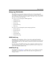
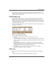
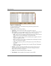
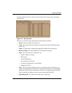
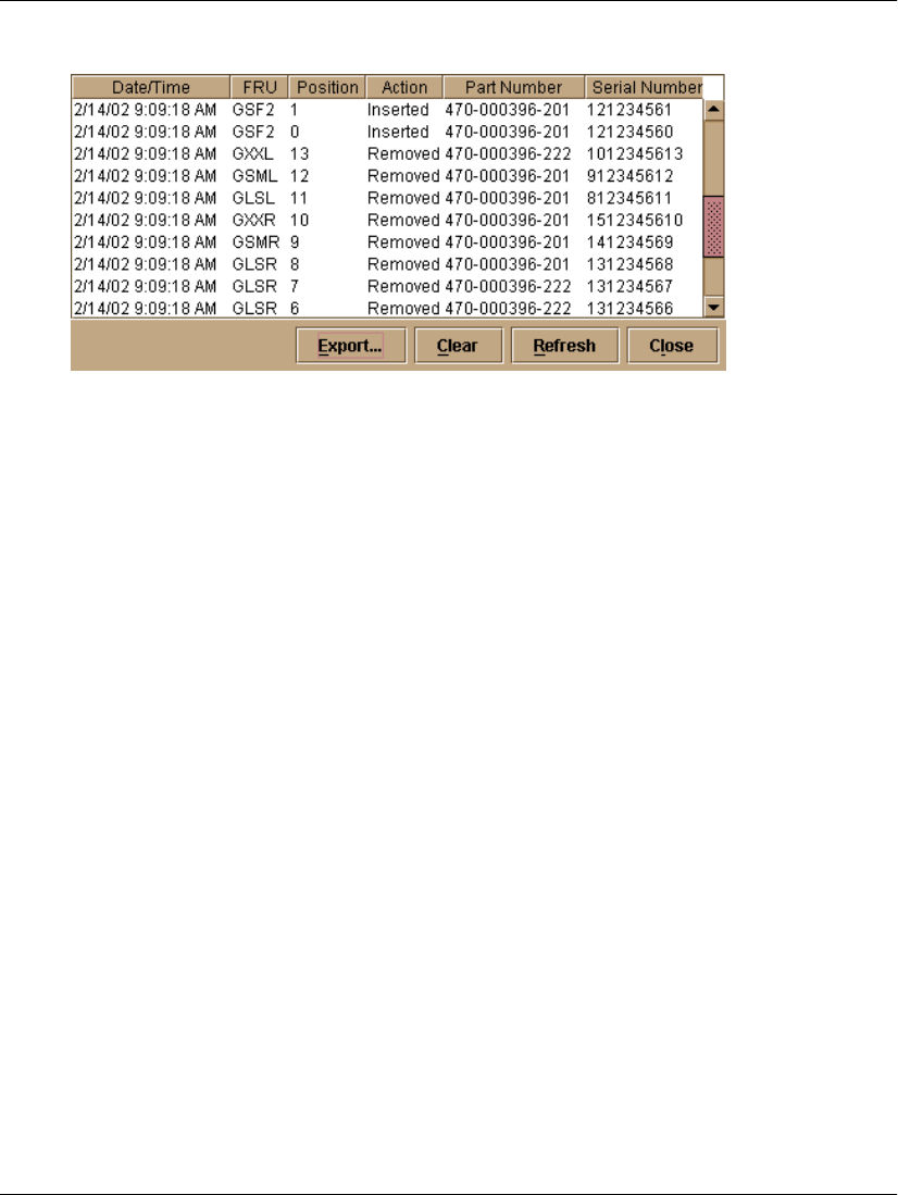
Figure 3–4: Hardware Log
To open the Hardware Log, select Hardware Log from the Logs menu on the
navigation control panel.
The log contains the following columns:
• Date/Time - the date and time the FRU was inserted or removed.
• FRU-Position - an acronym representing the FRU or non-FRU element, followed
by a number representing the FRU or chassis position. The acronyms are:
— SFP - Small form factor pluggable (SFP) optical transceiver. Chassis slots for
SFPs inserted in a port are 0 through 15. The SFPs are FRUs.
— PWR - power supply. Chassis slots for redundant power supplies are 0 and 1.
The power supplies are FRUs.
— FAN - cooling fan. Chassis slots for redundant fans are 0 through 5 (cooling
fans). The cooling fans are FRUs.
— CTP - control processor (CTP) card. The chassis slot is 0. The CTP card is
not a FRU.
— THM - thermal sensor. The chassis slot is 0 (on the CTP card). The thermal
sensor is not a FRU.
• Position - a number representing the FRU chassis position. Chassis slots for
power supplies are 0 and 1. Chassis slots for fans are 0 through 5 inclusive.
Chassis slots for SFPs are 0 through 15.
• Action - the action performed (Inserted or Removed).
• Part Number - the part number of the inserted or removed FRU.