


3–20 edge switch 2/16 service manual
Repair Information
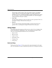
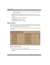
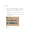
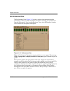
Hardware View
The Hardware View (Figure 3–11) displays a representation of and associated
information about a specified switch. This information is useful to maintenance
personnel for port-specific fault isolation and repair verification, link incidents, and
port segmentation problems.
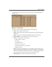
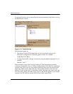
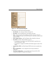
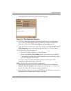
• Port operational state information from the Port Properties dialog box
(Figure 3–12).
• Port LED behavior that emulates the operational status of the corresponding real
switch. Refer to Table 1–1 on page 1-24 for an explanation of green and amber
LED behavior.
• Colored alert symbols (yellow triangle or red diamond with yellow background)
that indicate port status. Refer to Table 1–1 on page 1-24 for an explanation of
alert symbol indications.
Figure 3–11: Hardware View
Click the port connector (leftmost port) to open the Port Properties dialog box
(Figure 3–12).